DIY printhead
Posted by johnrpm
|
DIY printhead July 26, 2010 04:00AM |
Registered: 13 years ago Posts: 406 |
2 or 3 years ago I played around with making a peizo print head, whilst rummaging through some draws I came across a bag with the bits inside and thought it might be worth sharing, someone may be interested?.
I searched for peizo materials and found them to be to expensive for diy, so looked for an alternative and found bimorphes
at about 50p each, (buzzers), on a visit to my local poundland I purchased 3 bicycle buzzers to get the bimorphs as well as the drive electronics, the electronics are quit simple, a pulse generator feeding into a miniature step up transformer.
Version one consisted of a 30mm dia ally disc with a pocket to receive the bimorph and fluid, a hole in the top and the smallest hole I could drill opposite, I then closed the small hole with a ball bearing and hammer, connected it up to the cycle buzzer, added water and, "nothing", after some head scratching I tried white spirit instead, (first thing that came to hand),
"nothing", more head scratching, then added a reservoir in the form of a syringe without the plunger, success, I then tried vodka, again success but water would not go through.
I decided to make a better housing with the bimorph in the horizontal plane and build a driver and not rely on the cycle buzzer,
I used the insert from a spray can for the nozzle, a ne555 into a small transformer for the driver, I can vary the frequency and amplitude, the nozzle hole could do with being smaller but the results are very encouraging, its interesting to see the liquid spray out, as the frequency varies so does the spray pattern.
The main reason for doing this was the desire to print fluids that a standard print head can not cope with, they tend to be very fussy about viscosity and give up the ghost at the slightest excuse, a single printhead will never be as fast but mounted on a plotter above a powder bed similar to reprap, and using skeinforge or similar ??????.
If anyone is even slightly interested I will post some images, my ancient digital camera looses battery power within minutes.
|
Re: DIY printhead July 26, 2010 04:17AM |
Admin Registered: 17 years ago Posts: 1,791 |
It sounds interesting. What sort of resolution can you achieve?
-Sebastien, RepRap.org library gnome.
Remember, you're all RepRap developers (once you've joined the super-secret developer mailing list), and the wiki, RepRap.org, [reprap.org] is for everyone and everything!
-Sebastien, RepRap.org library gnome.
Remember, you're all RepRap developers (once you've joined the super-secret developer mailing list), and the wiki, RepRap.org, [reprap.org] is for everyone and everything!
|
Re: DIY printhead July 26, 2010 05:55AM |
Registered: 13 years ago Posts: 406 |
I did not get as far as measuring resolution, just getting the concept to work, the resolution would depend on the nozzle
size mainly I suppose, as well as frequency and amplitude, I intend to revisit this project when time permits, as I believe that the binder is critical to the final strength of parts, and standard printheads limit the materials they can pass through.
I will charge my camera and post images so that others can have a go if they wish.
|
Re: DIY printhead July 26, 2010 12:56PM |
Registered: 14 years ago Posts: 8 |
|
Re: DIY printhead July 26, 2010 02:37PM |
Admin Registered: 17 years ago Posts: 1,791 |
I will charge my camera and post images so that others can have a go if they wish.
Cool! Would you like to put them in the wiki so that they become official documentation (™)?
Here's a good place: http://reprap.org/mediawiki/index.php?title=Scratchbuilt_Peizo_Printhead&action=edit&redlink=1
You may want to use scaffolding from http://reprap.org/wiki/Example.
-Sebastien, RepRap.org library gnome.
Remember, you're all RepRap developers (once you've joined the super-secret developer mailing list), and the wiki, RepRap.org, [reprap.org] is for everyone and everything!
|
Re: DIY printhead July 26, 2010 04:38PM |
Registered: 13 years ago Posts: 406 |
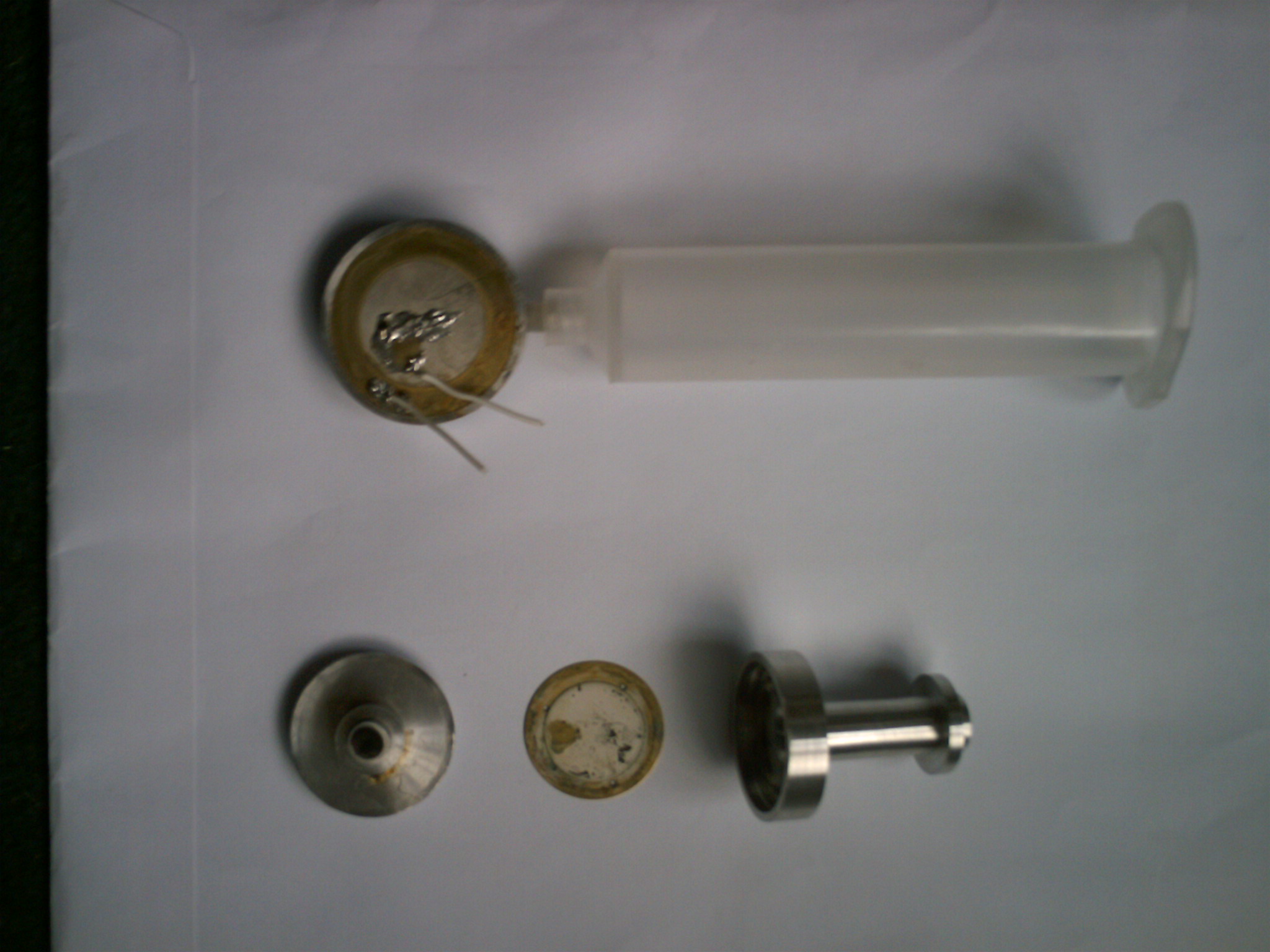
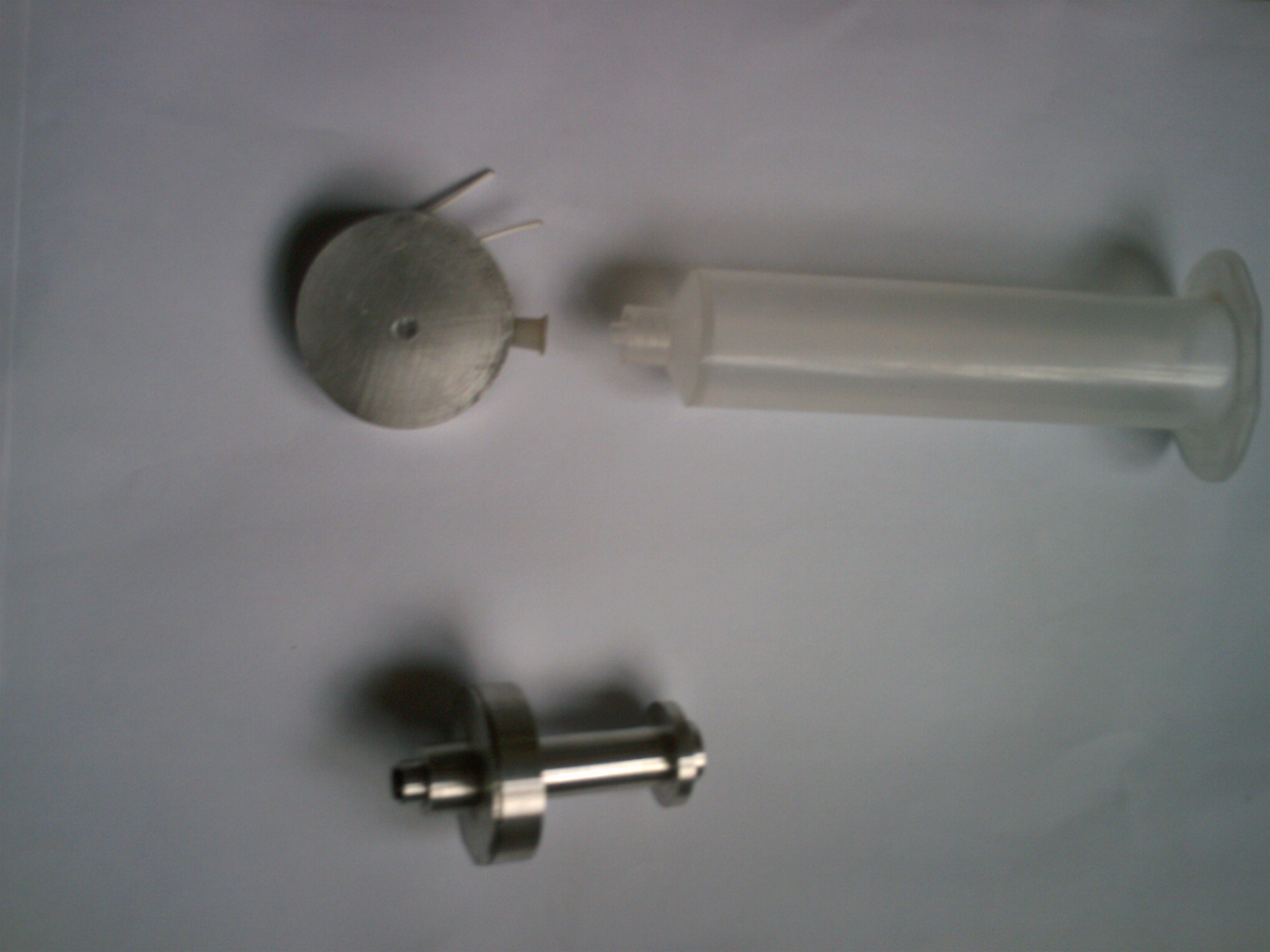
Sorry the images are so bad, my camera gave up the ghost and I had to lash up an old webcam,
version one at the top still works well, it was just glued together, the syringe body gives a head to stop
the fluid oscilating, the nozzle was drilled about .5mm and closed with a small ball bearing hit with a hammer
but I do not know the hole size at present, maybe around .1mm to .2mm ?.
The lower one is version two, it did work well but will need a new bimorph due to dismantleing for the images,
I drilled 3 small holes in the brass area for the fluid to pass through and used nail varnish to seal it,
the front cap is a light press fit, I remember looking at different spray can nozzles, some atomize better
than others, cutting them up with side cutters i found that some had an insert, I used one in version 2
|
Re: DIY printhead July 26, 2010 04:55PM |
Registered: 13 years ago Posts: 406 |
When I sort out the camera situation I would be happy to add stuff to the wiki if you think
it worthwhile,
The origonal concept was to form a cup shape to 2 bimorphs and solder them back to back to get
more force, but bending them cracks the crystaline material, but with a small press tool restricted
to the brass surround it should work, I used a standard transformer for the step up and it seems to
work ok, but I have since salvaged from the skip some high frequency transformers, an audio amp could
be used to drive them perhaps.
Bimorphs come in different sizes and frequencies, and they are so cheap its no big deal if you destroy one,
so you can test to the limit, but maybe there are other sources of piezo materials that are affordable for DIY ,
|
Re: DIY printhead July 26, 2010 10:43PM |
Registered: 14 years ago Posts: 196 |
|
Re: DIY printhead July 27, 2010 03:16AM |
Registered: 13 years ago Posts: 406 |
Assuming it all works , ( hopefully the result of community effort) it should be possible to print wax if the head is heated
and fed with molten wax, but that is some way down the line, I literally only spent about a week on this at least 2 years ago, so
can not tell it as a finished story, I had forgotten about it until I found the bag of bits, I have followed reprap for a long time and know how creative the community are, and as I support open source/ hardware wanted to share it.
P.S I suppose I will have to spend my hard earned money and get a camera this weekend, I dismantled a sampling machine
a while ago and the mechanics are a testament to compact design, it would make a good repstrap, I will post images
of it at some point.
|
Re: DIY printhead July 29, 2010 03:56AM |
Registered: 13 years ago Posts: 406 |
I have started on the wiki page, scratch built piezo print head and added it to the development list, its a work in progress and has already taken more time than the actual experiments, I will re-do the experiments and take images this time, I also added my mistmaker observations as it is also a piezo unit.
Edited 1 time(s). Last edit at 07/29/2010 03:59AM by johnrpm.
Edited 1 time(s). Last edit at 07/29/2010 03:59AM by johnrpm.
|
Re: DIY printhead August 02, 2010 10:30AM |
Registered: 14 years ago Posts: 356 |
I think your work is very important for everyone and for RepRap project. Right now it is a 3D printer (also a plotter) and in the future in can be a 2D ink printer.
When I tried to print my PCBs using an Epson printer, I verified that people really needs to be able to build their own printers because:
- we need to get cheap printing, because actual business of printers lock us with printer cartridges;
- people need to print on t-shirts, wood, PCBs, etc and not only just in paper (1) (2);
I am more interested on PCBs, because I verified that Epson DuraBrite ink resists very well to water and finger press!! It must work very well against enchant.
I will be following your work, on wiki page and this forum message. I will try to help when I can, maybe testing some hardware. I am ready to build an electronics company and we plan to commercialize (and Open Source for sure) a RepRap board with ARM 32bits @ 100MHz. I would love to help prototype and commercialize the electronics for your print head.
At RepRap, I believe there are users that have knowledge and tools to make the mechanical parts and others the electronics, like the 0.5mm nozzle (mechanical) or the electronics boards. For this project I could help on some part of the electronics but I can't on mechanical and so I need that someone could provide me a prototype of your print head.
As for electronics, could you please document/make a schematic? (please use KiCad if possible because is OpenSource and good).
People is being working with Arduino and piezos, so they should be easy to find and cheap.
Edited 3 time(s). Last edit at 08/02/2010 10:41AM by casainho.
---
New cutting edge RepRap electronics, ARM 32 bits @ 100MHz runs RepRap @ 725mm/s:
[www.3dprinting-r2c2.com]
|
Re: DIY printhead August 03, 2010 03:43AM |
Registered: 13 years ago Posts: 406 |
Hello Casainho,
Version one is as simple as it gets, a piece of alluminium machined to take the size of bimorph you are using, with a pocket to take the fluid, I did not do any maths, just by instinct, maybe the volume of fluid plays a part and I was lucky, but if you keep it to a minimum it may be better, the tricky bit is the small hole, by placing a ball bearing over the hole and hitting it with a hammer it reduces the size, if you go to far, (like I did) you then have to open it up again, I used to be into horology many years ago so had some watch reamers, these are seriously small square taper reamers, (it may be possible to use watch jewels as the hole).
Again the electronics are simple, I am not good enough at electronics to tell others, but I used a duel 555 to make a simple
pulse generator and the output goes into the transformer, if say you get 5 volts out of the 555, then you will need a transformer
with a ratio of 20 to get 100 volts, I would choose 25 or 30 for future use.
When I have time I will put some (refill) ink in the head and try to show the output, the jet itself is hard to see but the result on paper should give an idea, I will just move some paper about under the head whilst it is working, I hope the results are good enough?.
|
Re: DIY printhead August 03, 2010 04:15AM |
Registered: 14 years ago Posts: 356 |
I think a video showing it printing would be nice so we could understand. Please see if you can get a good borrowed machine ;-)
I bought my nozzle/heater barrel from reifsnyderb on Ebay, he is selling drilled nozzles with 0.25mm. Maybe we can ask him for help to make such a small drill?
Could you please make a mechanical sketch/design of your printhead? maybe later we could ask to sellers/users/hackers as reifsnyderb for a prototype. Can you produce a prototype?
About that cheap piezos, I already tested one and found that it could generate about 100V or 150V while I "kick" it. That voltage almost disappears if I put some load. I put an LED directly to that 100V and the LED quickly turned on when I "kick" the piezo.
So, piezo may have high input impedance. I believe that transformer your are talking can be easily prototyped and also that square wave, which we can make with a microcontroller, maybe a PWM output and vary the frequency and duty cycle.
Since I understand by your description on wiki page, if we have a 6kHz signal we should have a smooth jet. What if we need to quickly stop that jet? we just need to stop the signal? And to start the jet, the same? will the ink remain on printhead if there is none signal?
I don't understand how the input of the ink/liquid management is done. Is there any valve that just let's pass the liquid in the input direction?
On RepRap, we can't start/stop quickly the molten plastic filament from extruding, that's why I would like to know if we could do it with ink and your printhead.
Amplitude... this effects the distance the jet travels, and again appears pretty linear in response, going from 0 to 110 volts on the dial results in the jet traveling from 0 to 150mm.
150mm seems a lot to me!! We should have no need of 150mm but maybe 10 or 20mm will be enough.
If we have a circuit that have a square wave of PWM, duty-cycle 50%, frequency 5kHz, 12V (jet travel of 16mm??), it should work, no? we just need to use a mosfet to switch on/off a 12V signal. What do you think?
If we have that hardware + firmware working, maybe we can attach them to RepRap and control it using the software/gcode we are using for plotting.
Edited 3 time(s). Last edit at 08/03/2010 05:06AM by casainho.
---
New cutting edge RepRap electronics, ARM 32 bits @ 100MHz runs RepRap @ 725mm/s:
[www.3dprinting-r2c2.com]
|
Re: DIY printhead August 03, 2010 08:20AM |
Registered: 13 years ago Posts: 406 |
I am sorry if I have not explained it well enough, I am glad to see someone get involved I will add some more to the wiki when I get time.
like the fool I am, I tried to make the nozzle even smaller but ruined it in the process, so am looking at using hypodermic
needles, the sort that screw in, and cutting the end from the syringe tube and fixing it to the body, this would allow quick change nozzles, but not sure what the smallest size bore is yet.
Could you please make a mechanical sketch/design of your printhead
Yes will do
I believe that transformer your are talking can be easily prototyped and also that square wave,
I would try a high frequency one, the sort from computer power supplies, not steel laminates but.
Since I understand by your description on wiki page, if we have a 6kHz signal we should have a smooth jet. What if we need to quickly stop that jet? we just need to stop the signal? And to start the jet, the same? will the ink remain on printhead if there is none signal?
I don't understand how the input of the ink/liquid management is done. Is there any valve that just let's pass the liquid in the input direction?
No valves, just a tube from the reservoir to the head.
6Kh is on the dial on my box but thats not calibrated, the size and frequency of the bimorph will effect that number, so make your box have variable outputs to tune it, the reservoir needs to be set at the right height, too high and drips form, to low add it starves the printhead.
On RepRap, we can't start/stop quickly the molten plastic filament from extruding, that's why I would like to know if we could do it with ink and your printhead.
I tried just tapping the wire as quickly as possible and it reacted instantly as far as I could see.
If we have a circuit that have a square wave of PWM, duty-cycle 50%, frequency 5kHz, 12V (jet travel of 16mm??), it should work, no? we just need to use a mosfet to switch on/off a 12V signal. What do you think?
Yes I think that would work, the duty cycle should dictate the flow rate, but I am no expert on electronics, I have read somewhere that the signal is better with a slow decay to stop air being sucked back through the nozzle, but that may
be with high end drivers,
Can you produce a prototype?
You can have version2, As I said it needs a new nozzle but you are welcome to play with it, I shall make a new one.
|
Re: DIY printhead August 03, 2010 01:32PM |
Registered: 14 years ago Posts: 356 |
johnrpm Wrote:
-------------------------------------------------------
> Could you please make a mechanical sketch/design
> of your printhead
> Yes will do
I saw it on wiki, it's ok I guess. But what if someone want to reproduce it? are any measures/dimensions that you found important? -- like you didn't characterized yet very well the nozzle hole, can you please do it? what is your guess, lower than 0.25mm?
> I tried just tapping the wire as quickly as
> possible and it reacted instantly as far as I
> could see.
You mean that if we close with a valve the feed pipe it should be enough to stop the print (other than also stop electronic signal)?
> Can you produce a prototype?
> You can have version2, As I said it needs a new
> nozzle but you are welcome to play with it, I
> shall make a new one.
I think it's important to get something simple, cheap and DIY, so others can replicate and test/use and report. So I guess someone (you??) should define, characterize the printhead (at least the mechanical part).
Maybe as motivation, you could be interested in produce and sell the mechanical parts. What do you think? (there are others selling the mechanical parts on Ebay for RepRap).
---
I went to 2 local stores and I found the piezo in the same product (I don't remember but I think it is a 12V buzzer). I took 2 pictures and later I hope to turn it on and verify the signals on the small board:
Edited 3 time(s). Last edit at 08/03/2010 01:46PM by casainho.
---
New cutting edge RepRap electronics, ARM 32 bits @ 100MHz runs RepRap @ 725mm/s:
[www.3dprinting-r2c2.com]
-------------------------------------------------------
> Could you please make a mechanical sketch/design
> of your printhead
> Yes will do
I saw it on wiki, it's ok I guess. But what if someone want to reproduce it? are any measures/dimensions that you found important? -- like you didn't characterized yet very well the nozzle hole, can you please do it? what is your guess, lower than 0.25mm?
> I tried just tapping the wire as quickly as
> possible and it reacted instantly as far as I
> could see.
You mean that if we close with a valve the feed pipe it should be enough to stop the print (other than also stop electronic signal)?
> Can you produce a prototype?
> You can have version2, As I said it needs a new
> nozzle but you are welcome to play with it, I
> shall make a new one.
I think it's important to get something simple, cheap and DIY, so others can replicate and test/use and report. So I guess someone (you??) should define, characterize the printhead (at least the mechanical part).
Maybe as motivation, you could be interested in produce and sell the mechanical parts. What do you think? (there are others selling the mechanical parts on Ebay for RepRap).
---
I went to 2 local stores and I found the piezo in the same product (I don't remember but I think it is a 12V buzzer). I took 2 pictures and later I hope to turn it on and verify the signals on the small board:


Edited 3 time(s). Last edit at 08/03/2010 01:46PM by casainho.
---
New cutting edge RepRap electronics, ARM 32 bits @ 100MHz runs RepRap @ 725mm/s:
[www.3dprinting-r2c2.com]
|
Re: DIY printhead August 03, 2010 05:23PM |
Registered: 14 years ago Posts: 356 |
I just wrote a blog message telling about the current state of development, want we think we will need, the potential and asking for help: [casainho-emcrepstrap.blogspot.com]
[reprap.org] ??? --- it's not "Peizo" Sebastien, it's "Piezo" ;-)
---
New cutting edge RepRap electronics, ARM 32 bits @ 100MHz runs RepRap @ 725mm/s:
[www.3dprinting-r2c2.com]
[reprap.org] ??? --- it's not "Peizo" Sebastien, it's "Piezo" ;-)
---
New cutting edge RepRap electronics, ARM 32 bits @ 100MHz runs RepRap @ 725mm/s:
[www.3dprinting-r2c2.com]
|
Re: DIY printhead August 04, 2010 03:41AM |
Registered: 13 years ago Posts: 406 |
I saw it on wiki, it's ok I guess.
I think we are at the early stages with this, and don't want to spend lots of time documenting stuff that I do not consider good enough, I have started vesion 3, I have cut the end from a 10ml syringe, (plastipak), it has the taper also a quarter turn thread to accept needles, I like the thought of being able to change the nozzle quickly, I can not find a suitable piece of alluminium for
the new body so will have to order some.
The nozzle size size is probably as small as .1 or .2mm, but its hard to give an accurate size looking at it through a glass,
the nozzle size will depend on the material viscosity I think, for inks it can be small but for resins or varnish the resistance will be higher, so may have to be bigger?, thats why I want to try the syringe thing.
You mean that if we close with a valve the feed pipe it should be enough to stop the print (other than also stop electronic signal)?
I have not tried a valve, I suppose it would starve the flow but then their would be a slight delay whilst the fluid fills, just stopping and starting the signal stops and starts the jet I have found.
I think it's important to get something simple, cheap and DIY, so others can replicate and test/use and report. So I guess someone (you??) should define, characterize the printhead (at least the mechanical part).
I would rather get things as good as we can, then try to simplify and make as cheap as possible, I use alluminium but plastic should work?, it may be reprapable apart from the nozzle?.
Maybe as motivation, you could be interested in produce and sell the mechanical parts. What do you think? (there are others selling the mechanical parts on Ebay for RepRap).
No thanks, my motivation is to help others, [forums.reprap.org] I have stated work on this.
I have looked at your blog, very good, I am OK with mechanical but rubbish at electronics, so the more help we get the better..
|
Re: DIY printhead August 04, 2010 05:00AM |
Registered: 14 years ago Posts: 356 |
johnrpm Wrote:
-------------------------------------------------------
> I saw it on wiki, it's ok I guess.
> I think we are at the early stages with this, and
> don't want to spend lots of time documenting stuff
> that I do not consider good enough, I have started
> vesion 3, I have cut the end from a 10ml syringe,
> (plastipak), it has the taper also a quarter turn
> thread to accept needles, I like the thought of
> being able to change the nozzle quickly, I can not
> find a suitable piece of alluminium for
> the new body so will have to order some.
I will wait for your reports :-)
> The nozzle size size is probably as small as .1 or
> .2mm, but its hard to give an accurate size
> looking at it through a glass,
> the nozzle size will depend on the material
> viscosity I think, for inks it can be small but
> for resins or varnish the resistance will be
> higher, so may have to be bigger?, thats why I
> want to try the syringe thing.
Ok, I will ask to reifsnyderb if he can drill such small holes.
> You mean that if we close with a valve the feed
> pipe it should be enough to stop the print (other
> than also stop electronic signal)?
> I have not tried a valve, I suppose it would
> starve the flow but then their would be a slight
> delay whilst the fluid fills, just stopping and
> starting the signal stops and starts the jet I
> have found.
Even better, I guess.
> Maybe as motivation, you could be interested in
> produce and sell the mechanical parts. What do you
> think? (there are others selling the mechanical
> parts on Ebay for RepRap).
> No thanks, my motivation is to help others,
> [forums.reprap.org] I
> have stated work on this.
I still think that developing this kind of technologies in Open Source way and helping others to access them, it's a big help to everyone.
> I have looked at your blog, very good, I am OK
> with mechanical but rubbish at electronics, so the
> more help we get the better..
You just need then to focus on mechanical and let the electronics with me. Please find a relative good prototype and send it to me, I will do the same with electronics!
---
New cutting edge RepRap electronics, ARM 32 bits @ 100MHz runs RepRap @ 725mm/s:
[www.3dprinting-r2c2.com]
|
Re: DIY printhead August 04, 2010 08:12AM |
Registered: 13 years ago Posts: 406 |
I will get vesion3 done as soon as possible, if it works I will send you one, the only fly in the ointment may be
the extra resistance from the needle, I can cut them shorter but we will see.
[www.medisave.co.uk]
Edit,
Their are two types of syringe body adapter, one type just has a taper and the other has the same taper but with a thread to ensure a tight fit, on close inspection it appears there is a gap between the ends of the tapers, this is bad news, the gap would fill with fluid and interfere with the flow, a bit like putting something over the nozzle, what a shame, It would have been a neat solution, so far the only problem bit with this project has been the nozzles.
As an apprentice I was sent to the stores for a glass hammer, a long weight and some 1/4 bsf holes, I still need some holes.
Edited 2 time(s). Last edit at 08/05/2010 03:24AM by johnrpm.
|
Re: DIY printhead August 05, 2010 05:36AM |
Registered: 14 years ago Posts: 356 |
On oscilloscope I saw:
Looks to me that the middle pin of the piezo is a feedback signal that goes to circuit. When that signal goes over 0.7V, that 3 pins ic may be a transistor, and it turns ON, switching the positive wire of the piezo to GND. So this is the way to get an very simple and cheap oscillator, making the piezo to buzz. It works with low voltages of 3.3V, 5V and 12V(when I took that oscilloscope screens).
The frequency of the oscillation should be done by the resistors values and the characteristics of that transistor.
The sine wave of feedback signal is interesting, because the piezo is excited with a square wave but looks like is reaction is slow and so vibrates in in sine wave instead of that square wave.
Next I did measure the black and red wires signals when I "kicked" the piezo and the oscilloscope registered the energy generated:
Edited 1 time(s). Last edit at 08/05/2010 05:36AM by casainho.
---
New cutting edge RepRap electronics, ARM 32 bits @ 100MHz runs RepRap @ 725mm/s:
[www.3dprinting-r2c2.com]


Looks to me that the middle pin of the piezo is a feedback signal that goes to circuit. When that signal goes over 0.7V, that 3 pins ic may be a transistor, and it turns ON, switching the positive wire of the piezo to GND. So this is the way to get an very simple and cheap oscillator, making the piezo to buzz. It works with low voltages of 3.3V, 5V and 12V(when I took that oscilloscope screens).
The frequency of the oscillation should be done by the resistors values and the characteristics of that transistor.
The sine wave of feedback signal is interesting, because the piezo is excited with a square wave but looks like is reaction is slow and so vibrates in in sine wave instead of that square wave.
Next I did measure the black and red wires signals when I "kicked" the piezo and the oscilloscope registered the energy generated:


Edited 1 time(s). Last edit at 08/05/2010 05:36AM by casainho.
---
New cutting edge RepRap electronics, ARM 32 bits @ 100MHz runs RepRap @ 725mm/s:
[www.3dprinting-r2c2.com]
|
Re: DIY printhead August 05, 2010 05:43AM |
Registered: 14 years ago Posts: 356 |
I announced this idea and asked for others join if they were interested, and I got this message:
If you want to make a single nozzle print head that will take almost any ink or
paint then you will want to go with a pressurized system. They are easy to make
and easy to expand to multiple nozzle systems. A few years back I did a system
that had seven nozzles. I think your trying to put this on a CNC system. If this
is the case then the spacing of each color nozzle will be the offset in your CNC
program. You going to start with one head so you will not have an offset. Here
is how the simple printer and head is made. Get a plastic bottle and drill two
holes in the lid then put fitting in the holes so hoses can be connected to
them. On of the fitting will also have a metal tube connected to it that will
reaches to the bottom of the bottle. Now get a Loveshaw Cpjl00-001-0 micro valve
and connect a plastic tubing from the bottle fitting that has the metal tubing
that goes to the bottom of the bottle to then in port of the micro valve.
Connect a plastic tubing to the out port of the micro valve to a nozzle and to a
nozzle. The nozzle is nothing more then a small pipe that will fit into the
plastic tubing that has been filled with epoxy while having a wire in the center
of it the desired nozzle orifice size that has been waxed. When the epoxy is
cured pull the wire out and that is your nozzle. The last thing that you need to
do is connect a few pounds to air pressure to the other fitting on the bottle. 3
to 5 PSI is goof don’t use more then 7 PSI. The micro valve works on 5 VDC.
When
5VDC is applied to the micro valve the pressure will push ink or paint from the
bottle. One more note the Plastic tubing between the micro valve and the nozzle
should be as short as possible. If you want to get a supply of these micro
valves your best be would to buy a Marsh print head off of eBay. The print head
would give you seven micro valves, seven plastic tubing print nozzles.
---
New cutting edge RepRap electronics, ARM 32 bits @ 100MHz runs RepRap @ 725mm/s:
[www.3dprinting-r2c2.com]
|
Re: DIY printhead August 05, 2010 07:24AM |
Admin Registered: 17 years ago Posts: 7,879 |
The frequency will be mainly determined by the resonant frequency of the piezo, not the resistors, and that is why you get a sine wave. The piezo is vibrating with SHM and the transistor is giving it a kick at the right point in the cycle. It is like pushing a child on a swing.
[www.hydraraptor.blogspot.com]
[www.hydraraptor.blogspot.com]
|
Re: DIY printhead August 05, 2010 02:28PM |
Registered: 14 years ago Posts: 356 |


The attached file is how a basic single nozzle printer is made using a CNC with
a pulse to step drives. If your drives step on any pulse high or low then you’ll
need a different circuit. If the CNC step commands are 5vdc then this circuit
works if it is more then 5vdc then a voltage divider will be needed for each and
gate input. The voltage divider is nothing more then two resisters. I used the
Atmel microprocessor to do all the controlling back when I did my project a few
years ago. The microprocessor allows you to send all the enable step and
direction commands to it before it send them to the drives. This allows you to
write the printer valve delays in to the microprocessor code. Here is the big
hint how to add delays in a stream of pulses coming to the microprocessor.
Everything goes into shift registers. This allows you to insert and remove bits
states to turn on and off the printer valve. Every time a bit state changes on a
microprocessor pin you shift index the shift registers with the new valve. If no
action has accrued in a set amount of time make sure you turn off the printer
valve. I hopes this helps with your project.
Original message here.
Edited 1 time(s). Last edit at 08/05/2010 02:30PM by casainho.
---
New cutting edge RepRap electronics, ARM 32 bits @ 100MHz runs RepRap @ 725mm/s:
[www.3dprinting-r2c2.com]
|
Re: DIY printhead August 06, 2010 07:26PM |
Registered: 13 years ago Posts: 406 |
Update,
I made a new body using the syringe end, it does not work, the gap between the tapers, about 2mm spoils the flow, whilst fiddling with the dials and watching the void space, I could see the fluid turbulating but not getting out of the needle, I may revisit this at some point but have changed it to take a tapered insert, I drilled a .3mm hole in the insert and tried it, worked straight away but I closed the hole to about .2mm and tried refill ink, (magenta)
worked well, I can see the results a lot better but its messy, so the next thing is to try and get some video, then I will send you the head to play with
casainho if you still want to pursue it
I went to Maplins to get some more bimorphs, they have gone up from 50p to 80p, they only had 4, 1.8hz and 2, 4.2hz in the rack.
I have built similar pressurized systems similar to those above, but had a few issues, mainly to do with residual pressure, but all ideas are welcome.
Can anyone point me in the right direction with a circuit, at present I can tune the head for a good output with frequency and amplitude settings, and would like to regulate the flow or maybe do dots and dashes, at some point it must be linked to gcode, mach3 can output pulses, turn on a relay or send step and direction from the S command, I don't know what emc2 outputs or the extruder control on the arduino, I hope this makes sense to someone, I am stating to babble aren't I.
Edit, I also bought a book on 555 circuits but would like some advice from the experienced if possible.
Edited 1 time(s). Last edit at 08/06/2010 07:44PM by johnrpm.
|
Re: DIY printhead August 06, 2010 08:07PM |
Registered: 14 years ago Posts: 356 |
About the circuit, I think you should go simple and work with Arduino and power up the piezo directly from Arduino pin (5V) -- maybe with some diode in series or flyback to protect Arduino pin.
As for software tools to print, I would try to use Skeinforge to generates GCode paths from 3D shapes. Skeinforge would just make the first layer. On Arduino, every time I would have to turn the extruder ON (set_speed() > 0) I would turn ON instead the PWM signal on Arduino pin that goes to piezo. So, if (extruder_on) PWM_PIEZO_ON; else PWM_PIEZO_OFF;
Basically the software can be the same as for plotting.
I think before we go to firmware and software, you need to test the print head with 5V PWM signal. Does it do a jet? how many mm long?
How many time does it take to start and stop the jet?
Does a signal of 5V works? 12V? -- just need to go for 12V if 5V do not work.
What frequency and duty-cycle?
Edited 2 time(s). Last edit at 08/06/2010 08:11PM by casainho.
---
New cutting edge RepRap electronics, ARM 32 bits @ 100MHz runs RepRap @ 725mm/s:
[www.3dprinting-r2c2.com]
|
Re: DIY printhead August 07, 2010 07:29PM |
Registered: 13 years ago Posts: 406 |
I have been putting in a kitchen worktop today so have not had much time, but have set things up to do the video tomorrow, one thing worth mentioning is the relative height of the printhead and reservoir, by getting the reservoir at the correct height it avoids the formation of a small dome of ink on the face of the nozzle, which is blown of when the printhead is turned on.
About the circuit, I think you should go simple and work with Arduino and power up the piezo directly from Arduino pin (5V) -- maybe with some diode in series or flyback to protect Arduino pin.
I will look into this, it would make life easy but when I have tried low voltage the jet is more like a spray, then again I have been holding the paper by hand and moving it at different speeds and distances from the nozzle, if it were on a proper stand and under controlled conditions ?, I think that is going to be the next step.
As for software tools to print, I would try to use Skeinforge to generates GCode paths from 3D shapes. Skeinforge would just make the first layer. On Arduino, every time I would have to turn the extruder ON (set_speed() > 0) I would turn ON instead the PWM signal on Arduino pin that goes to piezo. So, if (extruder_on) PWM_PIEZO_ON; else PWM_PIEZO_OFF;
Definitely use skeinforge,
I think before we go to firmware and software, you need to test the print head with 5V PWM signal. Does it do a jet? how many mm long?
How many time does it take to start and stop the jet?
Does a signal of 5V works? 12V? -- just need to go for 12V if 5V do not work.
What frequency and duty-cycle?
To be done, If you email me your address I will send you the printhead for testing after doing the video, I will then make another.
|
Re: DIY printhead August 08, 2010 01:37AM |
Registered: 14 years ago Posts: 196 |
Johnrpm - Thank you for all of the information that you have posted concerning the details of your print heads.
My interest in experimenting with the print head is driven by the desire to experiment with making 3d prints using some of the powder recipes published by Open3DP.
I currently have a couple of piezo devices on order and I'm hoping to attempt to construct a print head based on your designs in the next week or two. As my RepStrap is EMC2 based, with the print head stepper driven directly from EMC2 as the A axis, I'm planning on experimenting with driving the piezo directly from the A axis step pulse.
If the drop size can be made small enough, I'm also interested in attempting to deposit materials for the construction of metal oxide based thin-film transistors, although that is a longer term interest.
If you do end up with any extra print heads you want others to try out I would be interested in trying one. I would be happy to cover any costs for parts, shipping, etc.
|
Re: DIY printhead August 08, 2010 05:08AM |
Registered: 13 years ago Posts: 406 |
I did the video early this morning and am figuring out how to add it, I see that vimeo is used by others, I just can not bear to have anymore logins and usernames, the video is rubbish but should give an idea,
Madscifi, I hope it comes up to expectations for what you want to do, it needs a lot of development for the intended application, some applications need dots whilst others need jets, I think the electronics will need to be created to allow the different modes, at present its a bit like a water tap full on, by messing around with the signal it should be possible to get control of the flowrate.
Bimorphs are just a start, I am sure that other piezo materials may be better, but bimorphs are a good starting point to learn the basics, for me the whole business of piezo was a black art, but when you start playing with things it all starts to make sense.
|
Re: DIY printhead August 08, 2010 05:59AM |
Registered: 14 years ago Posts: 356 |
This work is getting attention, I received on e-mail from RepRap admins saying:
> I've been watching some fun stuff bubbling up in the wiki
> wiki/XCbot
> wiki/Scratchbuilt_Peizo_Printhead
> wiki/Special:Contributions/Rocket_scientist
> (Tony's stuff)
> etc.
> (and I need to redo the front page to showcase stuff like this.)
Edited 1 time(s). Last edit at 08/08/2010 06:01AM by casainho.
---
New cutting edge RepRap electronics, ARM 32 bits @ 100MHz runs RepRap @ 725mm/s:
[www.3dprinting-r2c2.com]
|
Re: DIY printhead August 08, 2010 07:29AM |
Registered: 14 years ago Posts: 356 |
John, I put the video embedded on wiki page. I also added a feed to latest of this forum messages.
On that video, the line on the paper seems to be very large. Do you think it's because of the moving speed of the paper?
What was the hole diameter of the nozzle?
---
New cutting edge RepRap electronics, ARM 32 bits @ 100MHz runs RepRap @ 725mm/s:
[www.3dprinting-r2c2.com]
On that video, the line on the paper seems to be very large. Do you think it's because of the moving speed of the paper?
What was the hole diameter of the nozzle?
---
New cutting edge RepRap electronics, ARM 32 bits @ 100MHz runs RepRap @ 725mm/s:
[www.3dprinting-r2c2.com]

Sorry, only registered users may post in this forum.