Printtable
Posted by rklauco
|
Printtable July 11, 2016 04:36AM |
Registered: 8 years ago Posts: 181 |
Have you ever heard about this project?
I am in the very same situation - my Chinese i3 is enclosed in 2 LACK tables already.
And it seems very interesting to read about the idea of having printer made from the actual tables - it would allow me to make a very simple enclosure and increase the print volume.
What I found a bit "problematic" - the printer uses bowden, yet has the extruder motor at the hotend. I understand the disadvantages of bowden, but still, the added weight can be quite significant creating serious inertia.
Same applies to motor for X axis - having it at one side of the Y axis is not optimal according my opinion.
I'd suggest to go for H-bot or even CoreXY approach here.
The author seems to only build forum on his page for now, so I started the discussion here to get opinions of experienced builders.
|
Re: Printtable July 12, 2016 04:26AM |
Registered: 9 years ago Posts: 125 |
|
Re: Printtable July 12, 2016 05:30AM |
Registered: 8 years ago Posts: 181 |
|
Re: Printtable July 12, 2016 05:58AM |
Registered: 9 years ago Posts: 125 |
|
Re: Printtable August 08, 2016 08:09AM |
Registered: 8 years ago Posts: 181 |
So, I spent some time with Sketchup.
These are my results.
I made 2 types of them - one is with GT2 belt (quite long), indirect "semi-core-XY" - or how should I call it.
It's pretty straight forward.
The Z axis is not yet finished, but I am working on it.
I have the idea of having a big closed belt for 4 M8 threaded rods in 4 corners - but I am not sure this is the way I want it to be. I am not sure about the stability of 4 screws comparing to steel rods with bearings and actuation by threaded rod...
[github.com]
However, I also found a project called Sli3dr, which uses a nylon line for the actuation. I didn't believe it a lot, but I ordered the "rope" from aliexpress, just to see.
It's fantastically strong. And it tends not to stretch, although it's really a rope - it's made from 3-4 fibers.
And, what's more, it's exactly as thick as the M8 screw thread width.
So, what I tested is a rotating screw as an actuator for the string line - and it totally works. Just 3 threads and I was not able to "slip" it. So I designed this:
[github.com]
It's still a work in progress, but it should allow ~40 turns of the line on M8 thread - giving sufficient grab to move the gantry. And the resolution (calculated) is perfect.
Standard stepper with GT2 belt uses normally 20 tooth pulley. That means 40mm of belt for a single turn. As 1 turn is 200 stepper steps, that means I have resolution of 5 steps per mm, or in other words 0.2mm per step. With 16 microsteps I have 0.0125mm per step.
However, with M8 screw, the single turn is not 40mm, but more like 22mm - doubling it already. And, for X axis, the resolution will be double that - considering the line movement, you have to grab twice the length of the movement. So the real resolution will be 0.11mm per step with no microstepping for Y axis and 0.055 for X axis. With microstepping, it's even better.
My ball bearings arrived today morning, so I'll slowly start printing the parts and test the mechanics
But it already seem very interesting.
My plan (should the X and Y work) is to make Z axis using the same mechanism, too - remove the threaded rods, replace them with smooth rods and bearings and get the belt drive - same as X axis, but possibly with more "turns" for even better resolution on Z axis. Although eve 0.055 is plenty (...and when I engage microstepping...).
|
Re: Printtable December 10, 2016 03:00PM |
Registered: 8 years ago Posts: 181 |
Working on it for 4 months, this is preliminary result of 5th version.
I've tried using Slid3r derivative, but the length of belts was simply too long - tightening the properly made the whole construction too stiff and unmovable, loosening them resulted in poor movement precision.
So I've moved to direct driving the axes. I got inspired heavily from the original PrintTable.
However, there the author is selling the "improved version" and, from my perspective, this is a disaster. I tried to contact him, no answer. I asked even for money-back as the design is so bad, again, no answer. $13 lost...
He uses 12 bearings on Y axis, introducing a LOT of friction and noise - so he moved to extremely expansive ingus bearings - not what I had in mind when I decided to use cheap IKEA table as a main frame material...
So, my points:
- very small X axis assembly
- bowden extruder for lightweight printhead
- improved print dimensions (393x390x500mm)
- stiffer Z axis - 4 rods instead of 2, 4 threaded rods instead of 1
- RAMPS electronics with 128x64 display
- heat-bed powered by 230V, so no need for heavy duty power supply
The sketchup is kept in github and updated whenever I make significant step forward.
Current build images are attached.
|
Re: Printtable December 10, 2016 03:03PM |
Registered: 8 years ago Posts: 181 |
As a possible further plan I'll try to utilize the DC motors from 2D printers and encoders and make all 4 Z axis rods independent.
Using this, I'll be able to do precise Z axis calibration without anything else - the DC motor can "sense" the physical resistance of the printhead pushing against the glass bed and set it as maximum, then I'll move to the next corner and will do the same, and so on for all 4 corners.
This should allow for very precise and fast Z axis.
But it needs 4 motors, which I am not really happy about, so I am thinking about other options, too.
|
Re: Printtable January 15, 2017 03:24PM |
Registered: 8 years ago Posts: 181 |
So, I've got quite some progress.
I managed to get the printer more-or-less done.
Unfortunately, I travel tomorrow morning and I can't test it now as my kids are already sleeping, but I am VERY excited.
What works:
Visuals:
Anyone willing to help with advice or some effort is welcome! Sources are here: [github.com]
I uploaded the firmware, too, as I had to mod it a bit.
Plan for the future is to mod the X/Y and make it H-bot - I already started, but now I am focusing to make this one work first.
I managed to get the printer more-or-less done.
Unfortunately, I travel tomorrow morning and I can't test it now as my kids are already sleeping, but I am VERY excited.
What works:
- X axis - it's great. I'm very happy with the construction approach. The hotend is easily swappable, the fans are independent from the gantry. All that is remaining is to come up with some automitive-like connector so I can easily unplug all the wires.
- Y axis - here I am not as happy. The 608ZZ bearing I have is quite bad on the left side and it creates quite a lot of noise when moving. Mechanically it's ok, but the motor has to do extra effort to overcome the bearing resistance.
- Z axis - I finally managed to get it working. It was quite a pickle as there is 4 8mm rods and 8 lead screws. All of them are the cheapest and therefore all of them are a bit bent. To get it working required quite a lot of reverse bending, sanding, greasing, ... And again, the cheap 608ZZ on the bottom cause a bit of resistance, although nowhere near the Y axis. But, as there is a LOT of mechanical moving parts, the Z axis is quite loud. I like the homing to the bottom - makes a lot of sense and is easy to adjust the first layer without further mechanical adjustments of the end-stop.
- Extruder - I utilized a design from thingiverse and did slight modifications to enable filament sensor. I am not 100% satisfied with the double bowden as this causes quite a lot of resistance (overall length is more then 2m). I have to switch to some electrical conduit in the bottom part and leave bowden only at the top end. Possibly I will adjust the spool holder.
- Almost all the electronics - filament sensor is working, LCD display can be turned on/off with a button, all fans work as expected, hotend also works no problem.
- Spool holder - originally I thought I'll use 8mm steel balls, but it was LOUD as hell. Now I use 3 ball bearings, it's a bit quieter, but also more wobbly and I am not sure a swift pull will not kick the spool out of the line (especially with low amount of remaining filament).
- Extruder fan - I copied the design and it looked OK first, but now I realized I will need to mod it - change the zip-tie holder for a screw to make sure I can tighten it up properly. The speeds are quite dramatic...
- Heated bed - as I was not able to find suitable silicone heater, I decided to DIY it. I bought silicon heating wire (2pcs) with 75W power output both. I will use the glue for car exhaust to glue the wire in a zig-zag pattern to the bottom of the glass. We'll see how that works. But that has time, for sure.
- Endstops - while they work per-say, they are just glued in using hot glue. The plan is to use optical endstops, but that's gonna take some time.
- Wire management - right now it's a mess - just to make sure the electronics work OK.
Visuals:
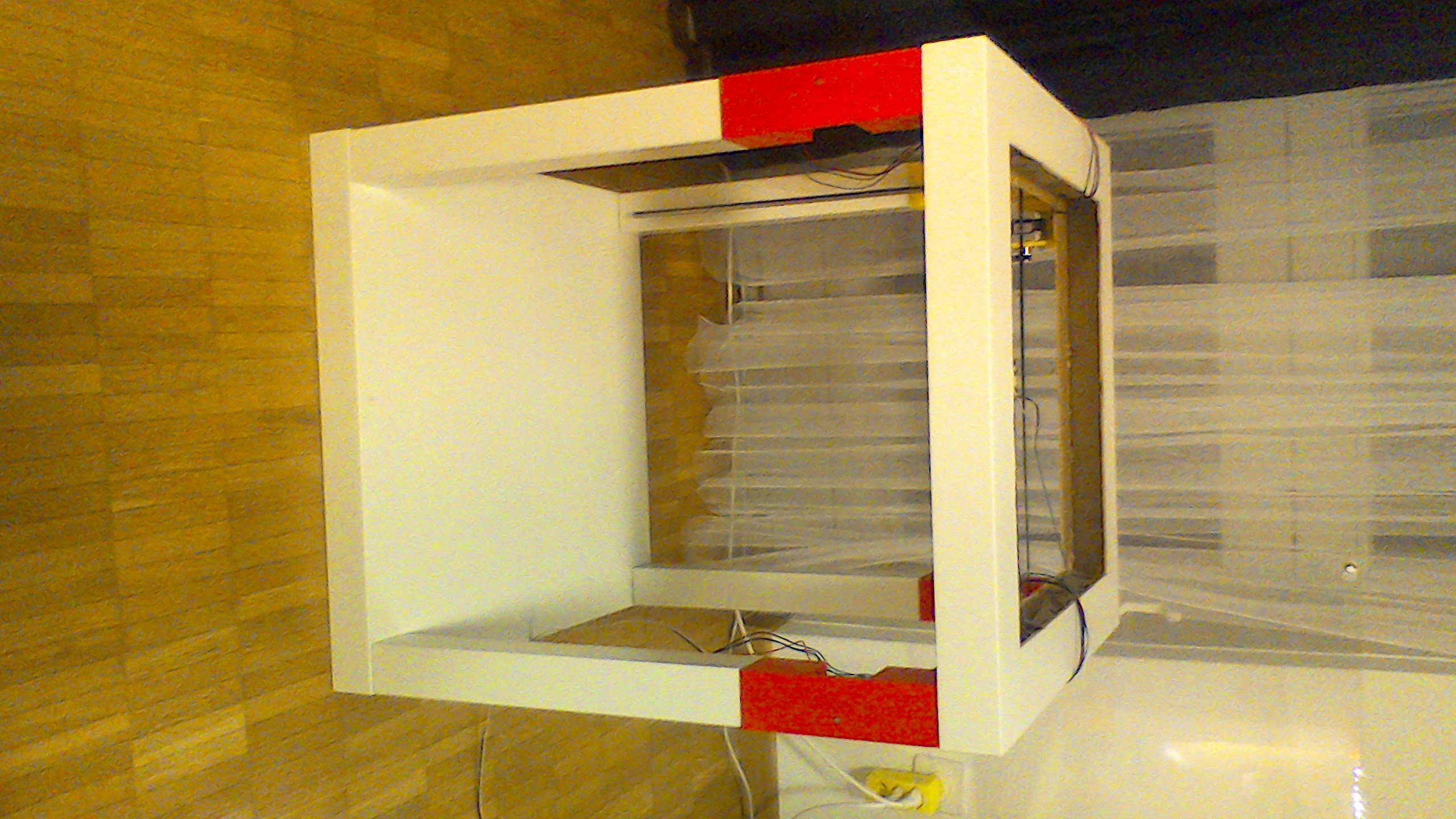
- Current status of the printer: [goo.gl]
- LCD display - the red button turns the backlight on/off: [goo.gl]
- Printbed almost at the bottom position: [goo.gl]
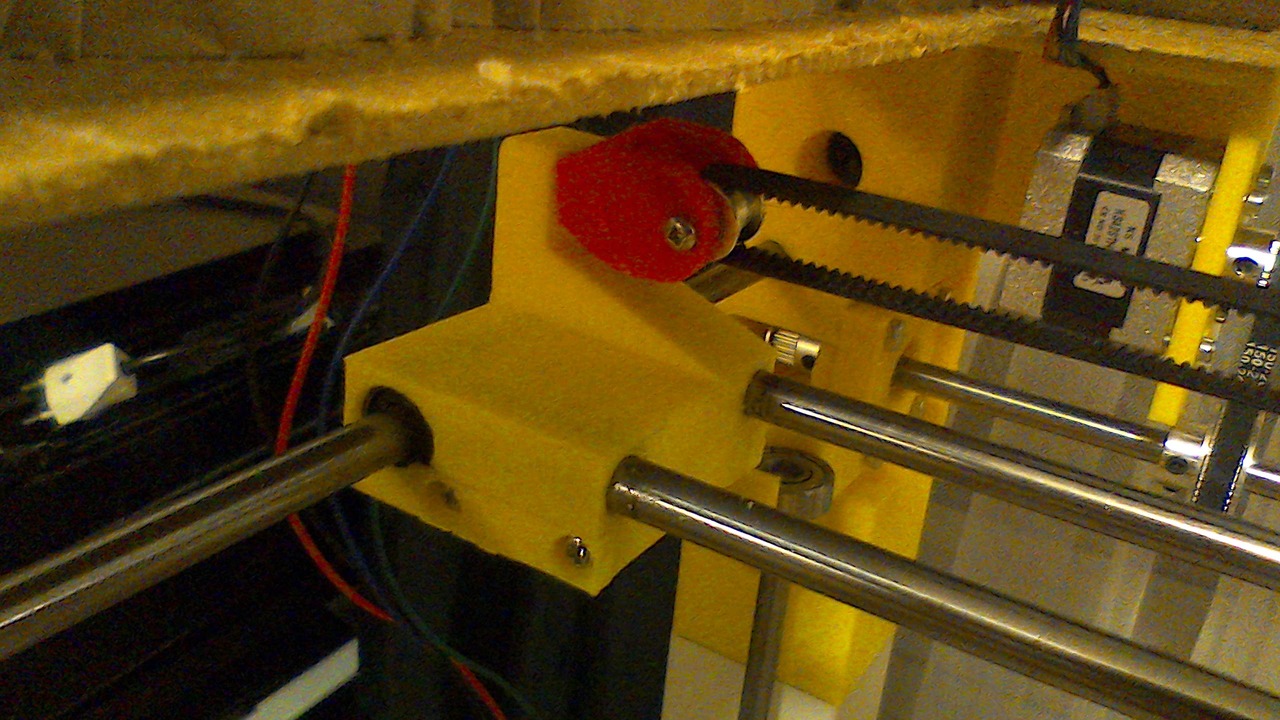
- Detail of bottom part of Z axis mechanics - all 4 corners are identical with the exception of endstop: [goo.gl]
- Detail of top part of Z axis mechanics - the 608 bearing is horrible and noisy there: [goo.gl]
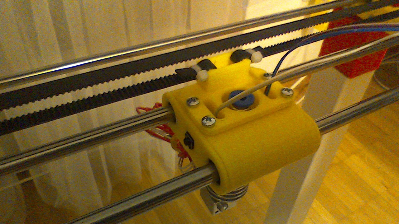
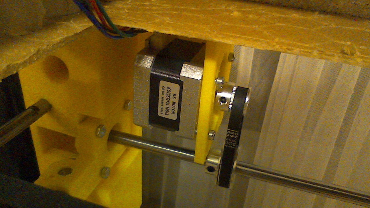
- X axis motor: [goo.gl]
- X gantry - visible is hotend (cheap e3d v5 clone), max endstop, bowden inlet and fans: [goo.gl]
- Extruder detail - the switch in the bottom part acts as filament sensor: [goo.gl]
- Horrible cable mess - RAMPS1.4, USB hub, MK802II with octoprint: [goo.gl]
- Y motor (out of focus, sorry): [goo.gl]
- Top table shielding - work in progress, already made covers with vent holes and with 40mm fan mount: [goo.gl]
- Temporary endstop mounts: [goo.gl] [goo.gl]
- Endstop on X gantry (this is Xmax): [goo.gl]
- Belt tensioning - X axis: [goo.gl]
- Belt tensioning - Y axis (out of focus): [goo.gl]
- Belt tensioning - Y axis - from outside (these are the only 2 screws visible outside for now): [goo.gl]
- Spool holder: [goo.gl]
- Detail of extruder cooler and part fans: [goo.gl]
Anyone willing to help with advice or some effort is welcome! Sources are here: [github.com]
I uploaded the firmware, too, as I had to mod it a bit.
Plan for the future is to mod the X/Y and make it H-bot - I already started, but now I am focusing to make this one work first.
|
Re: Printtable February 03, 2017 06:20PM |
Registered: 10 years ago Posts: 211 |
Wow, this seems really cool. Like it has been out for a while but this is the first I have seen or heard. Seems like you have been working on it for 6+ months rklauco?
I checked the latest pic, it looks really nice. I am contemplating building one or at least buy 2 tables and designing/building/moving a Prusa I3 into it. They sell the tables in yellow, which I really like.
Now that yours is together, how stable is the cube? Will there be any wobble or is it pretty steady?
I was contemplating NOT cutting out the center of the table, leaving the bottom and top fully enclosed in the nice table tops. Of course that would mean a different design, but I think it would wind up looking nice.
Are you using lm8uu or igus?
why did you go with lead screws in 4 corners vs just having 1 lead screw with 2 rods and a cantilevered bed?
The author evidently has a new version that does not require drilling holes in the table, maybe that is the updated version you speak of. Other than the author and you, I have not found others that have built these or blogged about them.
Keep going, I am interested to hear how well you can get yours working.
b
|
Re: Printtable February 04, 2017 12:21AM |
Registered: 10 years ago Posts: 211 |
|
Re: Printtable February 04, 2017 12:32AM |
Registered: 10 years ago Posts: 211 |
|
Re: Printtable February 04, 2017 03:18AM |
Registered: 8 years ago Posts: 181 |
Quote
n9jcv
rklauco ,
I am just gonna throw 2cents out there. If it were me, I think I would remove the bearings at the top of the z lead screws. Just let them float. That will eliminate the noise and from what I have read, z wobble is worse with constrained lead screws/5mm shaft.
b
The bearing is there from one particular reason - the Z axis is done differently as on other printers. Each side of the axis is not connected to the rest of the Z axis sides - therefore if the upper bearing is out, the whole 500mm shaft would just move left/right and instead of going up/down would just lock the lead screw.
I can try to make a short video to demonstrate the problem.
The solution would be to connect the Z-axis idlers with some material (e.g. some steel rod or something).
But the problem with Z axis is that it weights 4.5kg without the heating elements already, so adding further weight (4x450mm rods) would not help - the single NEMA17 motor would not be able to move it anymore.
|
Re: Printtable February 04, 2017 03:36AM |
Registered: 8 years ago Posts: 181 |
Yep, that may be about right.Quote
n9jcv
Wow, this seems really cool. Like it has been out for a while but this is the first I have seen or heard. Seems like you have been working on it for 6+ months rklauco?
It's pretty good. I was thinking about using some screws to stiffen it, but when I tighten the cam shaft mechanisms, the construction is quite rigid. So from my perspective, it's solid enough - I don't see any reason to make it stiffer.Quote
n9jcv
Now that yours is together, how stable is the cube? Will there be any wobble or is it pretty steady?
To cut the bottom part for the spool holder was a STUPID idea - so please, don't do itQuote
n9jcv
I was contemplating NOT cutting out the center of the table, leaving the bottom and top fully enclosed in the nice table tops. Of course that would mean a different design, but I think it would wind up looking nice.
The upper part is also questionable - I did it in the beginning, because I thought there will not be enough room for the filament bowden guide. And there wouldn't be. However, you can easily rotate the gantry upside-down and therefore shift the X/Y ~10cm down - that would allow enough room for the filament while allowing the upper part to stay solid. Funniest thing here is - even if you decide late, the new table from Ikea costs ~8USB around here, so no problem to change it Standard (cheapest) lm8uu. The whole partlist is here.Quote
n9jcv
Are you using lm8uu or igus?
Simple answer - Weight. The mirror alone is 4.5kg. Now add silicone, heater wire, any construction able to hold the 4.5kg and it's clear. Another reason is that if I was about to use cantilevered bed, I would have to use at least 2 bearings on Z axis, probably not LM8UU, but LM12UU (or even LU). Add a VERY beefy motor to the list (as the small NEMA17 would not be able to move it a bit) and you will jump with the price and the construction problems, too.Quote
n9jcv
why did you go with lead screws in 4 corners vs just having 1 lead screw with 2 rods and a cantilevered bed?
I am following the same approach - cam shafts instead of drilling holes and screwing. It's especially useful now in the design part, when it's relatively easy to disassemble and reassemble the whole machine. If I used wood screws, I would have to buy new table 4 times alreadyQuote
n9jcv
The author evidently has a new version that does not require drilling holes in the table, maybe that is the updated version you speak of. Other than the author and you, I have not found others that have built these or blogged about them.
The worst thing is - even the original author is not blogging about the printer. Although he claims in multiple videos that the project is open source, it's not. You can only get the STLs, not sources for them, he is not replying to any questions/comments, the forum part of the original website is "coming soon" for months and even buying the "newer" STLs from the author will not help you - I did, I found them "problematic" at best and when contacting the author I did not received a single line of reply.
Thanks. I constantly work on it - now that it actually prints it's much more interestingQuote
n9jcv
Keep going, I am interested to hear how well you can get yours working.
However, I realized with no heated bed it's useless - you can't print 300mm part even from PLA without heated bed as it will simply not stick 
So I am working on heated bed now - I purchased 2x20m of silicone wire, now I have to find a way how to attach it to the bottom of the mirror.
It's gonna be mains powered and will have selectable power output between 400 and 800W, so the heat-up times should be OK (remember, it's almost 4 times the size of some i3 printers).
Also, the printer is a bit noisier then I expected, so I am working on H-bot version now in parallel (although this effort is on a back burner until I finish the heated bed).
|
Re: Printtable February 04, 2017 03:41AM |
Registered: 8 years ago Posts: 181 |
ThanksQuote
n9jcv
by the way, I love the sketchup, that is AWESOME !!!! I don't think I could do that that is a very impressive sketch. So far I have just modeled individual parts, never an entire machine.
But comparing to folks like RichRap etc I'm just an amateur It's not that complicated at all, to be honest. As soon as you start to use components as model parts, it's easy.
I wanted to move from sketchup to something free and open such as FreeCAD, but I am struggling with it a lot - e.g. making a composed object out of 2 parametric copies is a nightmare. If I want to keep the component editable and linked to each other - it's no-go for me in FreeCAD
OpenSCAD would be better, but there it's pretty slow for me to invent from scratch - the simple push/pull in SketchUp is way faster.
I learn to live with few SketchUp problems that I encountered, so it works for me for now. We'll see how I manage in future

|
Re: Printtable February 04, 2017 05:41PM |
Registered: 10 years ago Posts: 211 |
|
Re: Printtable February 04, 2017 10:36PM |
Registered: 10 years ago Posts: 211 |
I see your spreadsheet list the cam nuts from Ikea. Do you have a part number for the cam nut and screw, or pic or measurements on them. I would like to pick some up. Also, do you have any pics/drawing on how to construct the cube like that. I can't envision how to put it together that way.
Thanks
b
Thanks
b
|
Re: Printtable February 04, 2017 10:43PM |
Registered: 10 years ago Posts: 211 |
|
Re: Printtable February 05, 2017 01:26AM |
Registered: 10 years ago Posts: 211 |
|
Re: Printtable February 05, 2017 08:18AM |
Registered: 8 years ago Posts: 181 |
Here is a demo video from the original PrintTable creator.
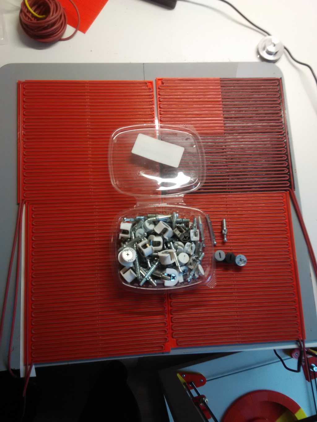
I used slightly bigger cams from IKEA. Here IKEA has something like "second hand" section where you can take a plastic box and buy as many construction elements as fits to the box for 2 or 4 CHF (~2-4 EUR). Attached is the picture of the smaller box for 2CHF.
I've got ~20 pcs of CAMs and screws of multiple lengths - shorter, longer, plastic, aluminum, ...
Oh, and the mess underneath the cam locks? That's the heating element for the printer - in progress
|
Re: Printtable February 05, 2017 09:18AM |
Registered: 8 years ago Posts: 181 |
Well, not my luckiest day.
On the mirror there was a tiny plastic foil on the backside to re-inforce it.
I decided to remove it prior gluing the heating element.
I was in the middle of the process, when a slight "pop" was heard - and the mirror broke to 2 pieces.
Well... I have to buy another one next week
On the mirror there was a tiny plastic foil on the backside to re-inforce it.
I decided to remove it prior gluing the heating element.
I was in the middle of the process, when a slight "pop" was heard - and the mirror broke to 2 pieces.
Well... I have to buy another one next week
|
Re: Printtable February 13, 2017 03:02PM |
Registered: 7 years ago Posts: 1 |
|
Re: Printtable February 13, 2017 03:07PM |
Registered: 8 years ago Posts: 181 |
Thanks
I finally went to IKEA today and bought the new mirror.
And also new set of filament arrived so I'll be able to print the new H-bot design and test it this week
I'll post new pictures afterwards.
I will also test the Chuck Hellybuck proposal - instead of heated bed to use thin sheet of acrylic (1mm thick) - let's see how that works for PLA.
|
Re: Printtable February 21, 2017 03:48PM |
Registered: 8 years ago Posts: 181 |
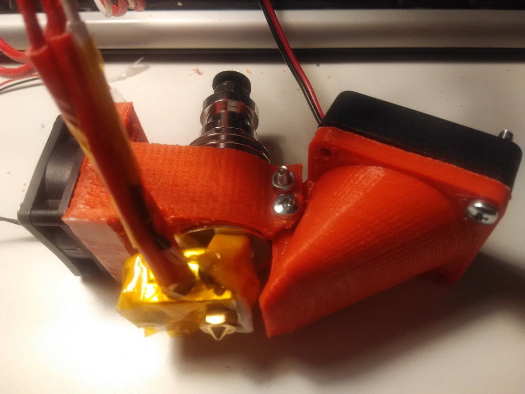
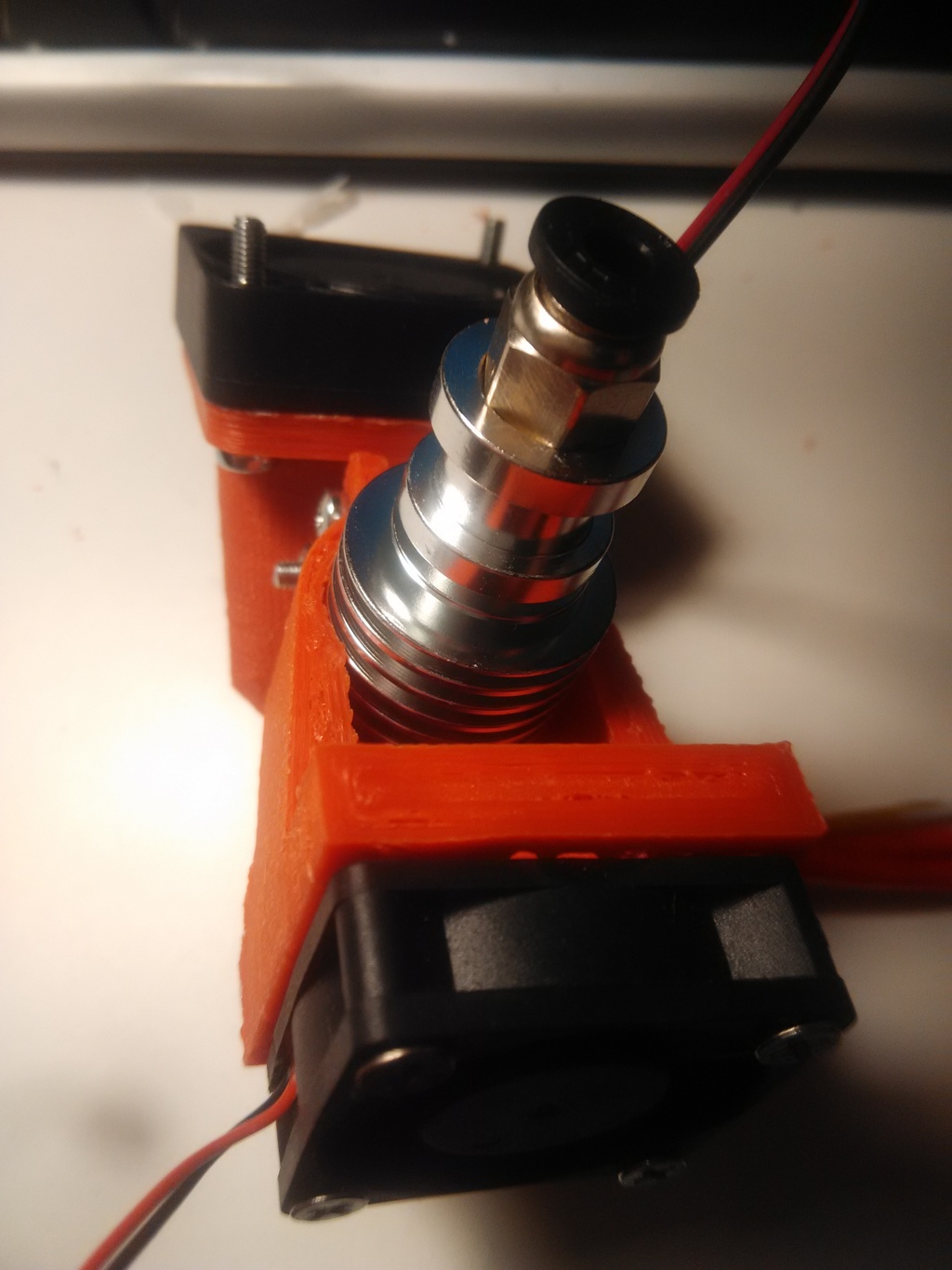
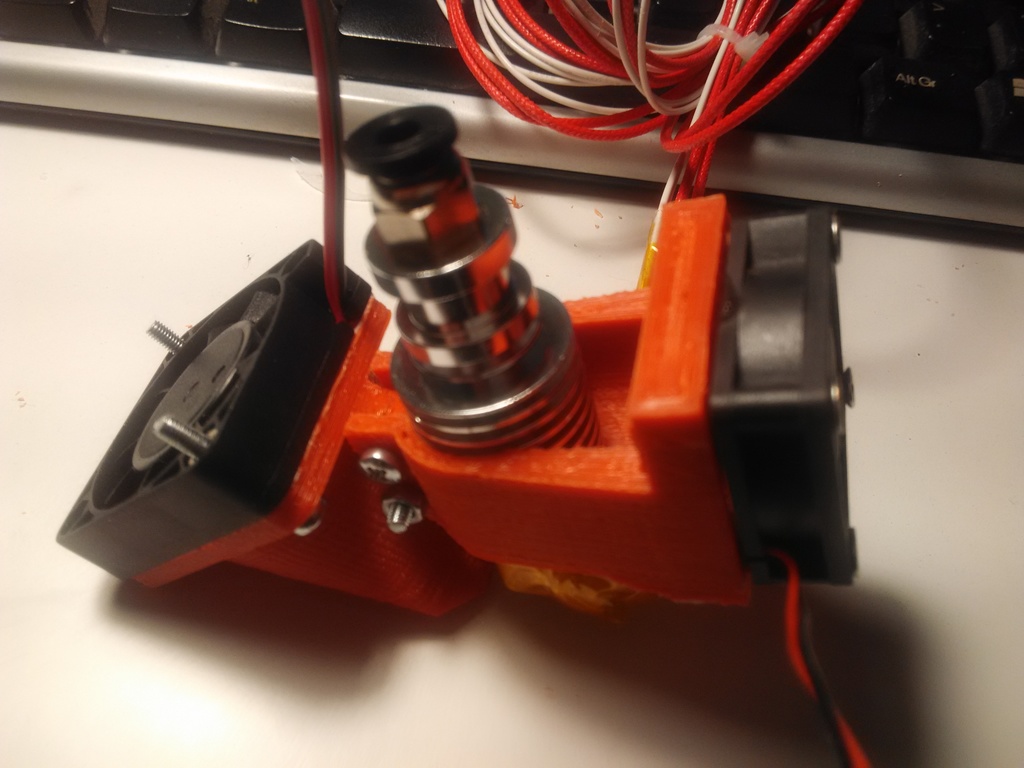
Acrylic sheet did not arrived, yet, but I've redesigned and printed new version of the hotend fan and extruder fan. Now it's just 1x40mm fan and 1x30mm fan, much easier and with much better mounting rigidity.
I need to buy 15mm M3 screws for this
I need to buy 15mm M3 screws for this
|
Re: Printtable February 28, 2017 01:52PM |
Registered: 12 years ago Posts: 548 |
|
Re: Printtable March 02, 2017 04:10PM |
Registered: 8 years ago Posts: 181 |
Good point, will try to do something about it.
However, now I am in a bit more trouble - I tried to do the H-bot version.
While it works, it's not ecstatic - the X axis wobbles a lot when changing XY direction - that's the known problem of H-bots.
So now I am working on some sort of CoreXY - we'll see. I'll print it tomorrow (17h print) and assemble it on Saturday.
|
Re: Printtable May 10, 2017 09:49PM |
Registered: 6 years ago Posts: 5 |
Sorry, only registered users may post in this forum.