new Open x carriage. Thoughts?
Posted by Buback
|
new Open x carriage. Thoughts? February 01, 2011 03:01PM |
Registered: 13 years ago Posts: 601 |
I find the standard sells x carriage very annoying. it's bulky and hard to assemble and has a very small opening ("bomb-bay?") for extruder hot ends.
So I designed a new carriage, and I need some input. Here's some pics of the prototype.
Those long bolts are all i had that would reach. i plan on flipping the bolts over and recessing the head, so m4-15 can reach.
Like the Sells carriage, it uses bearings, and uses one of the bars as the 'main' bar to do most of the constraining. the other bar is to carry the weight of the extruder and prevent rotation. Unlike the Sells the bearings are at 0, 90 and 210 degrees (instead of 90, 210, and 330) which allows the carriage to be snapped onto the bar without requiring major disassembly..
my prototype doesn't have mounting points or an attachment to the belt, but i have added mounting points to the 3d model. it is slightly more complex than my prototype, requiring overhangs in order to recess the M4 screw head. I haven't tried printing it yet.
For the belt attachment, i am thinking of a design i've seen in printers. which weaves the belt between 3 prongs. imagine pushing a comb onto the belt; i can integrate this type of thing into the 'arm' part very easily. the cut side of the belt could be tensioned with the zip tie method used in other designs.
the prototype carriage also has 3mm walls, which make it a bit springy. i bumped the design up to 4mm, but it is not meant to be solid as the Sells. I'm hoping that this won't present any problems.
I designed it in sketchup, so that's what i uploaded. the design is too complex for me to do in openscad. I can upload .stl s or whatever else i can export from sketchup if someone wants it.
Edited 1 time(s). Last edit at 02/02/2011 11:37AM by Buback.
So I designed a new carriage, and I need some input. Here's some pics of the prototype.


Those long bolts are all i had that would reach. i plan on flipping the bolts over and recessing the head, so m4-15 can reach.
Like the Sells carriage, it uses bearings, and uses one of the bars as the 'main' bar to do most of the constraining. the other bar is to carry the weight of the extruder and prevent rotation. Unlike the Sells the bearings are at 0, 90 and 210 degrees (instead of 90, 210, and 330) which allows the carriage to be snapped onto the bar without requiring major disassembly..
my prototype doesn't have mounting points or an attachment to the belt, but i have added mounting points to the 3d model. it is slightly more complex than my prototype, requiring overhangs in order to recess the M4 screw head. I haven't tried printing it yet.
For the belt attachment, i am thinking of a design i've seen in printers. which weaves the belt between 3 prongs. imagine pushing a comb onto the belt; i can integrate this type of thing into the 'arm' part very easily. the cut side of the belt could be tensioned with the zip tie method used in other designs.
the prototype carriage also has 3mm walls, which make it a bit springy. i bumped the design up to 4mm, but it is not meant to be solid as the Sells. I'm hoping that this won't present any problems.
I designed it in sketchup, so that's what i uploaded. the design is too complex for me to do in openscad. I can upload .stl s or whatever else i can export from sketchup if someone wants it.
Edited 1 time(s). Last edit at 02/02/2011 11:37AM by Buback.
|
Re: new Open x carriage. Thoughts? February 01, 2011 04:09PM |
Registered: 13 years ago Posts: 39 |
Hi Buback,
Please bear in mind my Mendel knowledge is currently pretty limited.
I really like the idea of hot swappable x-carriage, it would make tinkering with the extruder - even just removing it from the carriage - a much more relaxed affair.
Your lightweight design may prove the current over-engineered x-carriage is obsolete. With any luck it will anyway. I suspect that your material cutbacks, however, exacerbate a couple of limitations to extruded plastic objects.
Based on my limited material intuition:
Might you run longer bolts through the carriage, creating 'axles' between the bearings on either side? The bomb bay would get a little smaller, granted, but you might find that the axles work to counteract some of the springy quality you noticed in the carriage.
The original design has a capacity to tighten the x-carriage around its rails, in order to make up for inaccurate prints. You've opted to miss this feature out, presumably including reduced space for the x-axis bars as a standard, so the carriage can be 'clipped' on and off. Over the longer term, plastic must be given to sagging, especially in close proximity to heat and vibration. The additional pressure on the frame resulting from this clip on method may result in a loose carriage.
Largely over thoughtful guess-work on my part though. Overall I admire the simplicity of the concept, the printed part and it's assembly.
Woodsmoke
r:-4
|
Re: new Open x carriage. Thoughts? February 01, 2011 05:27PM |
Registered: 13 years ago Posts: 601 |
having an axle is defiantly feasible, and i was thinking of that early on. I opted for the m4-15 for now because that's what i have available, and because it doesn't require a trip to the hardware store if anybody wants to build it.
I can take 1mm off the carriage side of the arm part to allow for adjustment. this would then require putting washers in between the carriage and the arm. I don't think that the 0 and 90 degree bearings need any adjustment other than additional washers to center the bearings, which is what makes the 0/90 combo nice. I actually didn't reduce the size of the bearing rails, it's just built around 8 mm rods. now, my rails are extruded carbon fiber (i think 5/16) which if i recall correctly is just a hair under 8 mm, and it is still nice and tight. a valid concern, though.
One of the reason i wanted a more open carriage is so that i could better insulate the hot end. I also tried to remove all the pieces below the rails, in order to get plastic as far away from the hot end as possible. I'm hoping that with the extra space for more insulation, the hot plume that comes off the hot end will be significantly reduced. Even without insulation, the plume shouldn't have as many places to get trapped and will dissipate quicker.
However, like i said, my rails aren't metal, and the original design shields the rails from the hot end (albeit with plastic). my design might heat up the rails more if the hot end isn't insulated, sending the heat into the bearings, and causing warping there (maybe, who knows)
I think my current extruder mounting holes are maybe too flimsy. printing it now to find out.
|
Re: new Open x carriage. Thoughts? February 01, 2011 06:31PM |
Registered: 13 years ago Posts: 188 |
I have been working on a similar concept. My first design (http://www.thingiverse.com/thing:4944) was very open and light, but not so strong. It kept my insulator a bit cooler, but over time the front part began warping and it didn't hold the axis as well.
I'm now testing a more heavy-duty design. I have had to doctor several places because it didn't quite fit right and two of the posts broke due to poor layer adhesion. I hope to print a prettier one before crating a page for it, but you can see the general idea in the two pictures bellow.
I'm just using a couple of printed "snap-on" clamps to mount the extruder. You can see some pictures of the concept in the thingiverse page. That part has worked great, so you'll notice that I'm still using the same clamping mechanism. It keeps the extruder block from completely closing off air flow over the hot end, it was simple to make, and it pops off only when I strategically apply pressure to the clamps - tugging on the filament doesn't seem to bother it much.
I suggest that you keep an eye out for the thin parts of your carriage turning soft and flexing under heat. This was ultimately what made me replace my first design.
|
Re: new Open x carriage. Thoughts? February 01, 2011 07:08PM |
Registered: 14 years ago Posts: 1,092 |
Buback: I'd make the sides a little thicker than 4mm, possibly 5mm.
Also I'd try and make the 45 degree bends a little thicker again, as I think they'd be the part most affected by heat.
The single bearing in the middle underneath - Did you consider using a triangular piece to hold that in place, with a slot on one of the carriage attaching corners instead of a hole (for adjustment)? I suspect a single bolt attachment to the carriage could allow movement over time. Note that I suggest the slot is on one of the bolts that attach it to the carriage, NOT on the bearing, as then all the force is on one bolt that can slide in it's hole.
BTW: What material are you using? ABS or PLA?
|
Re: new Open x carriage. Thoughts? February 01, 2011 07:27PM |
Registered: 13 years ago Posts: 601 |
yes we are thinking along the same lines :-)
I know i'm trying to push the bounds here a bit with such a thin part. I assume that the parts are far enough away from the plume, but i'll have to experiment. Or perhaps i should learn from Icarus :-)
How thin are/were the pieces that distorted on your carriage? And which is the front part that you mention?
Actually i didn't intent for the carriage to snap on, but i was playing with it and a spare 8 mm steel rod and at one point the rod just slipped out (i was holding the carriage at the time). so then i tried snapping it on and it works like a charm! One worry i have is that, because my bars aren't steel, snapping the carriage on and off could scratch the surface and increase friction a bit. i don't think that would be a problem with steel rods. and it's really only one trio of bearings that "snap" on. i'll have to make a video eventually to explain.
|
Re: new Open x carriage. Thoughts? February 01, 2011 07:44PM |
Registered: 13 years ago Posts: 601 |
PLA, so the Icarus analogy stands :-)
In fact, originally I was thinking about an L shaped bracket, made from two pieces. It would be very simple to do that: just print out a second under carriage bracket. it would work something like an arm, with the shoulder being the fixed end, the bearing being at the elbow, and a slotted hole along the forearm. you would need a longer bolt than a m4-15, though, at the elbow and forearm, and the forearm attachment point would need a 4mm spacer where it attaches to the carriage.
that being said. i just didn't want to print it out. I don't even know if the carriage ever experiences large rotation forces about the x axis, anyway, especially if it is attached to the belt on the opposite side and the weight of the NEMA 17 on top. I haven't tried it yet though, so I'll report it if it does.
|
Re: new Open x carriage. Thoughts? February 02, 2011 01:50AM |
Registered: 14 years ago Posts: 1,092 |
A single piece rather than 2 makes sense then. One part would be straight (which replaces the existing part) and the other would be a curve with a (curved) slot in it.
Also, I notice you're using 9 bearings (6 on one side, 3 on the other).
Have you thought about trying to reduce the bearings on the 6 bearing side? ie: dropping one bearing and putting it's pair in the middle?
I'm thinking you could possibly drop the 2 bearings bolted on the side and replace it with just one, located right in the middle (rather than the sides). Moving any of the others could be more of a pain for your design IMHO.
Then again, that may wobble around too much.
|
Re: new Open x carriage. Thoughts? February 02, 2011 11:34AM |
Registered: 13 years ago Posts: 601 |
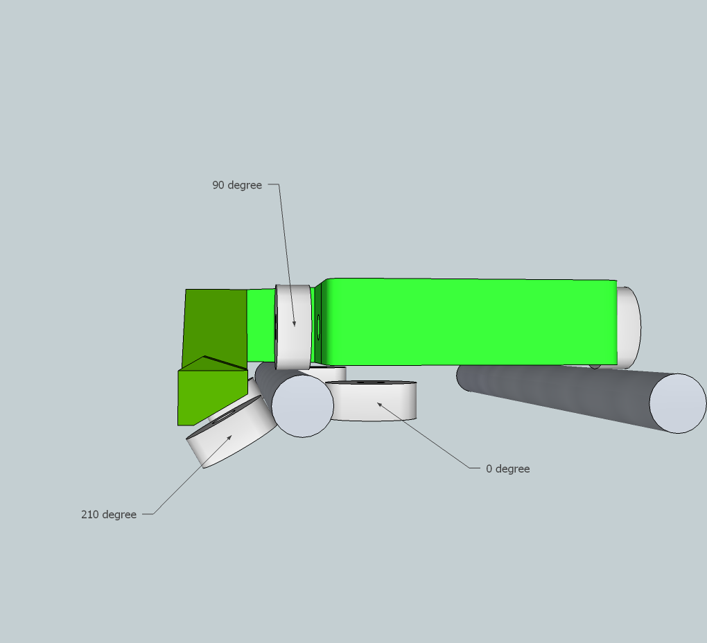
If I understand you right, your suggesting a single 210 degree bearing. I altered the file for this config.
I can also design the L bracket with a curved slot. that seems like a good design.
another thought to reduce bearings: you can use two of this new arm design, one on each side, and then remove the 0 degree bearings. this would then only require 6 bearings, but it might bind if the bars aren't parallel.
However, (and i haven't tested this yet) i kinda like having the bearings far away from the hot end. even my current underarm bearing is too close to the middle of the carriage for my liking. I worry that the bearing will heat up and start melting the plastic screw hole, leading to slop. I think this might be a bigger problem with metal rails and long print jobs.
on the other hand, the whole point is to have room to well insulate the hot end, and if done properly, hopefully the heat plume will not be an issue.
ps I attached a pic so you can understand which bearings i'm referring to.
|
Re: new Open x carriage. Thoughts? February 03, 2011 12:46AM |
Registered: 14 years ago Posts: 1,092 |
|
Re: new Open x carriage. Thoughts? February 03, 2011 02:47AM |
Registered: 13 years ago Posts: 601 |
i got it all assembled tonight (i'll post pics tomorrow) and took some temp measurements.
I use a heater block from mendel-parts, currently uninsulated, and a wades extruder. I put the mounting holes so that i could mount the wades sideways. i have a piece of 4 mm MDF on the bottom of the wades because the extruder has a PEEK block and 4 mm threaded rods, and i needed somewhere to attach the rods to. so anyway it ends up almost completely covering all the opening i've created, like a lid. i can put holes in the MDF and shape it better, but i attached it as is for testing, thinking it would be a worst case scenario.
My room is about 18C (65F, pretty cool) and when stationary, the temp under the carriage is around 60-65C max. This is with the heater block running at 200C. Printing at ABS temps would probably be too much for this design if printed in PLA. temps might max out at 75-85C which over time would warp the carriage. (the PLA wiki page posits that ~65C will start to effect PLA)
However, that is without insulation, stationary (not printing) and with the openings covered up. i think it can only get better. I do worry about the mounting holes, though. I would prefer to mount the extruder to the holes at the ends of the carriage, but i wanted to make something compatible with stock extruders.
|
Re: new Open x carriage. Thoughts? February 03, 2011 06:03AM |
Registered: 13 years ago Posts: 486 |
|
Re: new Open x carriage. Thoughts? February 03, 2011 11:54AM |
Registered: 13 years ago Posts: 601 |
Here are some pictures i took this morning:
Here it is with the extruder mounted. you can see in this picture that i inset the head of the 0 degree bolts so that i had an unobstructed flat surface on the top. I did this with conical holes, and it printed fine, but i still need to find the best angle. I'll probably do the arm with the same recessed heads. i gotta say that m4-15 bolts are mostly useless. (actually i guess the specs say 16 mm so i guess that's what i have)
I also had to add some washers between the arm and carriage, which you can just make out in this picture. it seemed like it was bending more with this newly printed carriage, so i added the washers to reduce the bending.
it's a bit out of frame, but you can see how I'm tensioning the belt in this pic. this technique is used elsewhere, i think on prusa?
This pic shows how the belt is connected to the carriage. I think the parts are too flimsy, and on the wiki page you can see my current design
Here you can see how open the hot end is now. With the original carriage, only about half of the heater block would peek out of the bottom.
I'm very happy with this, as it was my whole goal. Not only can i better insulate the hot end, but now i can also take better printing pictures for my friends, family, and all you guys.
ps. I think that i'll attach the carriage to the belt right next to the belt join/tensioner by spinning the carriage 180 degrees. another goal i have it to dampen the vibrations in the x belt on the unattached side, so I'll need to use the un-joined side (I'm thinking about just something to reach out from the carriage and press a bearing against the belt.)
pps. the wiki page is at http://reprap.org/wiki/OpenX
Edited 1 time(s). Last edit at 02/03/2011 12:00PM by Buback.

Here it is with the extruder mounted. you can see in this picture that i inset the head of the 0 degree bolts so that i had an unobstructed flat surface on the top. I did this with conical holes, and it printed fine, but i still need to find the best angle. I'll probably do the arm with the same recessed heads. i gotta say that m4-15 bolts are mostly useless. (actually i guess the specs say 16 mm so i guess that's what i have)
I also had to add some washers between the arm and carriage, which you can just make out in this picture. it seemed like it was bending more with this newly printed carriage, so i added the washers to reduce the bending.

it's a bit out of frame, but you can see how I'm tensioning the belt in this pic. this technique is used elsewhere, i think on prusa?

This pic shows how the belt is connected to the carriage. I think the parts are too flimsy, and on the wiki page you can see my current design

Here you can see how open the hot end is now. With the original carriage, only about half of the heater block would peek out of the bottom.
I'm very happy with this, as it was my whole goal. Not only can i better insulate the hot end, but now i can also take better printing pictures for my friends, family, and all you guys.
ps. I think that i'll attach the carriage to the belt right next to the belt join/tensioner by spinning the carriage 180 degrees. another goal i have it to dampen the vibrations in the x belt on the unattached side, so I'll need to use the un-joined side (I'm thinking about just something to reach out from the carriage and press a bearing against the belt.)
pps. the wiki page is at http://reprap.org/wiki/OpenX
Edited 1 time(s). Last edit at 02/03/2011 12:00PM by Buback.
|
Re: new Open x carriage. Thoughts? February 07, 2011 07:48PM |
Registered: 13 years ago Posts: 601 |
I've put up the stl's in a zip file on the wiki page, as well as build instructions and BOM. Click the link in the info box. Everytime i try to upload individual stl files, it says the file is corrupted? so i guess it's just the zip for now.
the carriage works like a charm!
Please someone print this out and give me some feedback. It will probably take about 3 hours to print, but i was only printing at 16mm/sec, so you might be done much faster.
here are some pictures of the final (for now) design.
in this picture you can see a revised design for what i previously called the 'comb' attachment. now it's just a tooth, shaped kinda like a simple house. you can see on the wiki page that it has a small flange to keep the belt from slipping off, although it shouldn't be a problem if the belt is tensioned.
The only other change i made is to recess the holes in some places. This might be a bit tricky to print for some people as it is an overhang, but it printed just fine for me, and i've only been printing for a month. it's not steeply overhanging, but just take note.
the carriage works like a charm!
Please someone print this out and give me some feedback. It will probably take about 3 hours to print, but i was only printing at 16mm/sec, so you might be done much faster.
here are some pictures of the final (for now) design.


in this picture you can see a revised design for what i previously called the 'comb' attachment. now it's just a tooth, shaped kinda like a simple house. you can see on the wiki page that it has a small flange to keep the belt from slipping off, although it shouldn't be a problem if the belt is tensioned.
The only other change i made is to recess the holes in some places. This might be a bit tricky to print for some people as it is an overhang, but it printed just fine for me, and i've only been printing for a month. it's not steeply overhanging, but just take note.
|
Re: new Open x carriage. Thoughts? February 07, 2011 10:25PM |
Registered: 13 years ago Posts: 1,780 |
|
Re: new Open x carriage. Thoughts? February 07, 2011 11:27PM |
Registered: 13 years ago Posts: 601 |
Just under 12cm from the bed to the rails. of course, the important distance is from the bed to the extruder, which is 9 cm. Still, it's much better than the regular perpendicular orientation.
I think the main room for improvement with the wades is making it thinner so that it will go between the top threaded rods.
(i like the simplicity and reliability of the block heater. If you want the best of both worlds, perhaps wrap the nichrome around an aluminum tube, and add interior threads, so that you can screw it onto the extruder nozzle?)
|
Re: new Open x carriage. Thoughts? February 08, 2011 09:41AM |
Registered: 16 years ago Posts: 438 |
Buback Wrote:
-------------------------------------------------------
> (i like the simplicity and reliability of the
> block heater. If you want the best of both worlds,
> perhaps wrap the nichrome around an aluminum tube,
> and add interior threads, so that you can screw it
> onto the extruder nozzle?)
That's been done. Though he used brass, and got a "threaded insert" which already had threads in it (inside and out, I thinkI, hard to tell from the pictures.)
--
I'm building it with Baling Wire
|
Re: new Open x carriage. Thoughts? February 11, 2011 05:19PM |
Registered: 13 years ago Posts: 601 |
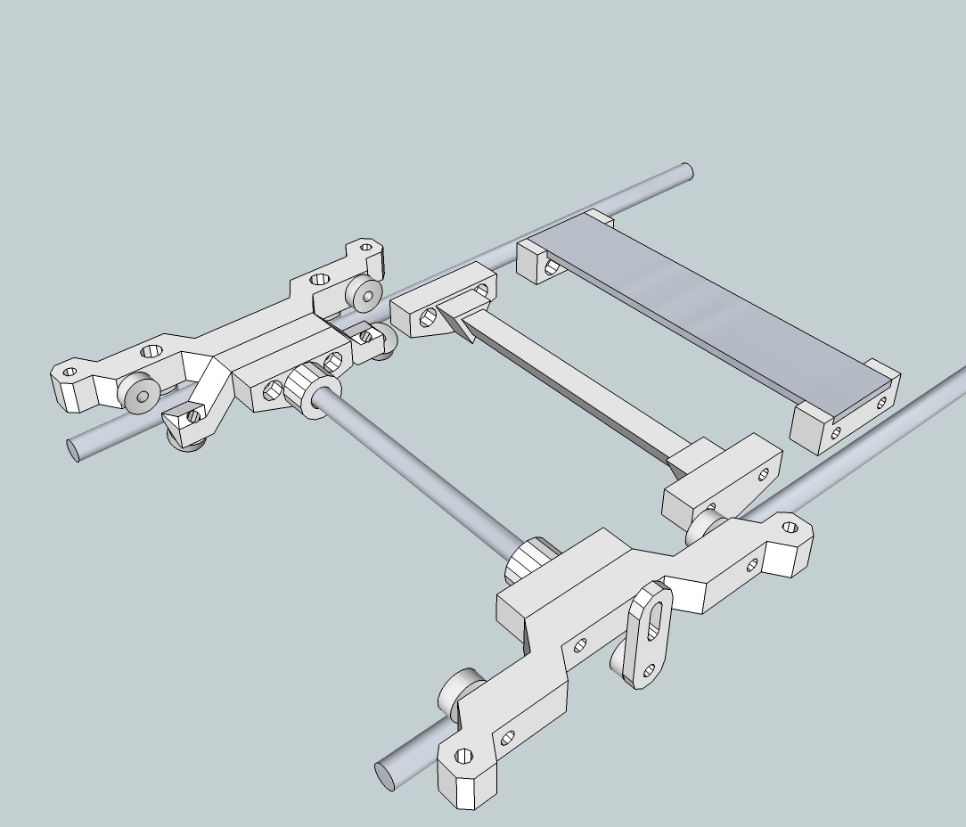
I was thinking of a redesign of the y axis as well, using similar components.
First idea is that i hate all those adjustment screws, and all those pockets for the bearings. Second idea is to get rid of the hard-to-cut squashed frog. i replaced the frog with just one m8 threaded bar.
I'm not entirely sure if using bar will make it lighter or heavier. defiantly less bearings (i still want bearings, not bushings). I might go back to a thick sheet if the bar is too heavy, but it would be a simple rectangle, not a frog. I think the bed will mainly keep the carriage square, but there needs to be some kind of crosspiece to attach the flag and belt to.
here is a picture of what i have so far:
the pieces are 120mm long (the frog is 130mm long)
(i have the bar in the center, which i think is probably best for transferring the force from the belt, but i could offset it some back/front so that the flag is closer to the sensor. maybe i should add another crossbar? maybe use M6 rod? If i use larger bearings, like 608s, for the top 4 weight bearing bearings, then i could have the crossbars also act as axles. the problem then, though is that the belt attachment point would then be high above where the belt usually is.
First idea is that i hate all those adjustment screws, and all those pockets for the bearings. Second idea is to get rid of the hard-to-cut squashed frog. i replaced the frog with just one m8 threaded bar.
I'm not entirely sure if using bar will make it lighter or heavier. defiantly less bearings (i still want bearings, not bushings). I might go back to a thick sheet if the bar is too heavy, but it would be a simple rectangle, not a frog. I think the bed will mainly keep the carriage square, but there needs to be some kind of crosspiece to attach the flag and belt to.
here is a picture of what i have so far:

the pieces are 120mm long (the frog is 130mm long)
(i have the bar in the center, which i think is probably best for transferring the force from the belt, but i could offset it some back/front so that the flag is closer to the sensor. maybe i should add another crossbar? maybe use M6 rod? If i use larger bearings, like 608s, for the top 4 weight bearing bearings, then i could have the crossbars also act as axles. the problem then, though is that the belt attachment point would then be high above where the belt usually is.
|
Re: new Open x carriage. Thoughts? February 11, 2011 05:51PM |
Registered: 13 years ago Posts: 188 |
I would suggest putting a small radius in the plastic parts to make sure that the rod doesn't slip down the axis. Maybe you can clamp it tight enough that it won't be a problem, but a radius to hold it in place would guarantee that it doesn't move as the belt jerks it back and forth.
If you are relying on the build plate itself as a structural component, I would think that would be enough to keep the slides squared up. I don't think extra bars would help much unless a heated build plate causes the plastic to soften or creep.
If you are relying on the build plate itself as a structural component, I would think that would be enough to keep the slides squared up. I don't think extra bars would help much unless a heated build plate causes the plastic to soften or creep.
|
Re: new Open x carriage. Thoughts? February 14, 2011 04:16PM |
Registered: 13 years ago Posts: 601 |
I was thinking of making an RP part to hold the ends of the rod, maybe like this:
But i'm not sure if bar will be best. maybe it's better to use flat aluminum bar, like a meter stick. it's about 30 mm wide and 3-4 mm thick. it would require drilling holes in it, probably two in each side to attach to the bearing arms, and at least two for a optoflag/belt attachment RP part, certainly less work than cutting out a squashed frog. it would be lighter than a solid rod and the nuts, etc..
on the other hand, I was also thinking of using unthreaded rod or tube, as this allows a wider range of materials, like extruded carbon fiber or aluminum tubing. perhaps a teardrop attachment like with the Prusa x axis would be enough to prevent it from rotating? the rod rotating is only a problem for the opto flag, because if it tilts up and down a little bit it will throw off the home position. but each bed/print should be ok, unless your homing between each layer, in which case any discrepancy will result in layers being slightly misaligned.
If using unthreaded rod, i'm not sure the belt/opto RP piece has to be solidly coupled to the rod. The tension of the belt should hold it in place in the x direction, and parallel to the belt. here is the design i mocked up:
the flag would go through the 4mm hole, of course, and the belt would be kinked in a v shape, going over that little house-shaped protrusion. it would be tensioned by using zip ties.
if it works, there would be very few nuts/bolts, which always add more weight than you expect. it will also be much easier to assemble, as the rod just has to be cut to size, as opposed to cutting to size and drilling 6-8 holes. it might need a teardrop shaped hole for the 8mm rod and a small m3 screw/nut just to remove backlash between the hole and rod (to give some allowance for different printers print quality).
I also saw someone mention that perhaps it would be better to only have three bed adjustment screws. does anybody else agree, or is it better to support each corner of the bed? or can it be done both ways, with springs holding it up on each corner, but only 3 adjustment screws.
Edited 2 time(s). Last edit at 02/14/2011 04:21PM by Buback.

But i'm not sure if bar will be best. maybe it's better to use flat aluminum bar, like a meter stick. it's about 30 mm wide and 3-4 mm thick. it would require drilling holes in it, probably two in each side to attach to the bearing arms, and at least two for a optoflag/belt attachment RP part, certainly less work than cutting out a squashed frog. it would be lighter than a solid rod and the nuts, etc..
on the other hand, I was also thinking of using unthreaded rod or tube, as this allows a wider range of materials, like extruded carbon fiber or aluminum tubing. perhaps a teardrop attachment like with the Prusa x axis would be enough to prevent it from rotating? the rod rotating is only a problem for the opto flag, because if it tilts up and down a little bit it will throw off the home position. but each bed/print should be ok, unless your homing between each layer, in which case any discrepancy will result in layers being slightly misaligned.
If using unthreaded rod, i'm not sure the belt/opto RP piece has to be solidly coupled to the rod. The tension of the belt should hold it in place in the x direction, and parallel to the belt. here is the design i mocked up:

the flag would go through the 4mm hole, of course, and the belt would be kinked in a v shape, going over that little house-shaped protrusion. it would be tensioned by using zip ties.
if it works, there would be very few nuts/bolts, which always add more weight than you expect. it will also be much easier to assemble, as the rod just has to be cut to size, as opposed to cutting to size and drilling 6-8 holes. it might need a teardrop shaped hole for the 8mm rod and a small m3 screw/nut just to remove backlash between the hole and rod (to give some allowance for different printers print quality).
I also saw someone mention that perhaps it would be better to only have three bed adjustment screws. does anybody else agree, or is it better to support each corner of the bed? or can it be done both ways, with springs holding it up on each corner, but only 3 adjustment screws.
Edited 2 time(s). Last edit at 02/14/2011 04:21PM by Buback.
|
Re: new Open x carriage. Thoughts? February 14, 2011 06:56PM |
Registered: 13 years ago Posts: 1,780 |
Buback Wrote:
-------------------------------------------------------
> Just under 12cm from the bed to the rails. of
> course, the important distance is from the bed to
> the extruder, which is 9 cm. Still, it's much
> better than the regular perpendicular
> orientation.
Hmm. I can print a part as tall as 110 mm on my Mendel with Adrian's Geared extruder as long as I keep the X large enough (I think 30 mm is enough) to avoid the triangular frame. Otherwise, a little over 70 mm is all I can print if I want to use the whole bed.
> I think the main room for improvement with the
> wades is making it thinner so that it will go
> between the top threaded rods.
>
That would be nice if it could be done. But I thought that the motor would hit the top of the frame next.
|
Re: new Open x carriage. Thoughts? February 14, 2011 08:54PM |
Registered: 13 years ago Posts: 601 |
re: wades motor
yes it would. but perhaps by using a thinner NEMA 17 (22 instead of 48mm tall) it might fit. if you could go between the top rails, you could make the extruder body taller to accommodate a larger large gear. or maybe mount the regular stepper vertically?
just throwing out ideas.
and i didn't specify, but I the meant 12 cm from the bed to the x axis rails, with about a cm or less from the triangular frame members to the gear on the wades, mounted sideways. it goes even higher if you don't need to go under the triangular frame members. it's 150mm from the bed to the x rails. of course, it is cutting it awfully close for that measurement:
You can see i'd need to move some of the wires if i wanted to print this high. I need the MDF piece under the wades in order to mount the hot end, but if you don't, you get an extra 4mm.
Very little room, here.
You would only ever be able to wring another 30 mm out of the height. the x axis belt starts hitting the frame, and eventually the idler side of the x axis collides with the top. And even at the height in the pictures, i risk having the build hit my thick sheet that the controller board is mounted on.
Edited 1 time(s). Last edit at 02/14/2011 08:54PM by Buback.
yes it would. but perhaps by using a thinner NEMA 17 (22 instead of 48mm tall) it might fit. if you could go between the top rails, you could make the extruder body taller to accommodate a larger large gear. or maybe mount the regular stepper vertically?
just throwing out ideas.
and i didn't specify, but I the meant 12 cm from the bed to the x axis rails, with about a cm or less from the triangular frame members to the gear on the wades, mounted sideways. it goes even higher if you don't need to go under the triangular frame members. it's 150mm from the bed to the x rails. of course, it is cutting it awfully close for that measurement:

You can see i'd need to move some of the wires if i wanted to print this high. I need the MDF piece under the wades in order to mount the hot end, but if you don't, you get an extra 4mm.

Very little room, here.
You would only ever be able to wring another 30 mm out of the height. the x axis belt starts hitting the frame, and eventually the idler side of the x axis collides with the top. And even at the height in the pictures, i risk having the build hit my thick sheet that the controller board is mounted on.
Edited 1 time(s). Last edit at 02/14/2011 08:54PM by Buback.
|
Re: new Open x carriage. Thoughts? February 15, 2011 01:47PM |
Registered: 13 years ago Posts: 601 |
i'm making some progress on the y axis redesign. i'm going to go with the round unthreaded bar or tube for now:
the only reused piece from the openx work i did is the undercarriage bracket. I reused a lot of ideas from that x carriage, though, as you can probably tell.
the only piece i'm worried about printing is the one that holds the bearings at a slant. It has a semi-circular protrusion on it now so that the bar stays perpendicular, but it protrudes from the bed-side of the print (prints the bearing-side slant better, since it's not overhanging), so i'll probably have to make that into a separate piece.
The other issue i have is whether i should make the bed support hole position compatible with the regular bed. I suppose that's best for everyone. the parts might need funky protrusions in order to line them up right, though.
Edited 1 time(s). Last edit at 02/15/2011 01:56PM by Buback.
|
Re: new Open x carriage. Thoughts? February 16, 2011 11:47PM |
Registered: 13 years ago Posts: 601 |
I love this rapid prototyping!
Ok i'm pretty much settled on the design. it's a bit hard to see in the following pictures, but these are stacks of parts, not single parts.
I found that most round pencils are just about 8mm, at least here in the US (probably 5/16ths, but close enough). those should be rigid enough, and cheap/free and easy to source. all you do is cut it to 135 mm. pens are a bit too flimsy, and too short.
something more exotic might be needed if you have a heated bed, like glass tubing. But i don't really see any benefit of going with any type of metal. it will cost many times more then the pencil and likely weigh more.
the parts are stacked together and bolted. simple as that.
here's a sequence of me putting the carriage on the rails. pics are a bit over-exposed, but you get the idea:
as you can see it can be attached after the rails are in place, and taken off just as easily. the only thing i don't show here is attaching the undercarriage bearing, since i'm still working out the bed placement holes. I also didn't show the belt attachment, since i still need to print that out and test it.
All these pieces printed warp free with an unheated bed, but i'm using PLA. the two longest pieces are around 120 mm long. I have no experience with ABS, so i don't know how these pieces will print, and if they can be printed without warping.
a 4 mm particleboard squashed frog weighs 64g. the pencil cut to length weighs 4g!
I'm also using less and shorter screws. the regular y carriage uses 36 m4-40's, i use 8, plus 5 m4-15's.
currently it weighs 134g. i calculate that, for the regular y carriage, just the m4-40 screws alone (no nuts, bearings, or washers) will weigh about 144g!! (my stainless screws weigh 4g each)
Edited 2 time(s). Last edit at 02/17/2011 12:12AM by Buback.
Ok i'm pretty much settled on the design. it's a bit hard to see in the following pictures, but these are stacks of parts, not single parts.


I found that most round pencils are just about 8mm, at least here in the US (probably 5/16ths, but close enough). those should be rigid enough, and cheap/free and easy to source. all you do is cut it to 135 mm. pens are a bit too flimsy, and too short.
something more exotic might be needed if you have a heated bed, like glass tubing. But i don't really see any benefit of going with any type of metal. it will cost many times more then the pencil and likely weigh more.
the parts are stacked together and bolted. simple as that.
here's a sequence of me putting the carriage on the rails. pics are a bit over-exposed, but you get the idea:


as you can see it can be attached after the rails are in place, and taken off just as easily. the only thing i don't show here is attaching the undercarriage bearing, since i'm still working out the bed placement holes. I also didn't show the belt attachment, since i still need to print that out and test it.
All these pieces printed warp free with an unheated bed, but i'm using PLA. the two longest pieces are around 120 mm long. I have no experience with ABS, so i don't know how these pieces will print, and if they can be printed without warping.
a 4 mm particleboard squashed frog weighs 64g. the pencil cut to length weighs 4g!
I'm also using less and shorter screws. the regular y carriage uses 36 m4-40's, i use 8, plus 5 m4-15's.
currently it weighs 134g. i calculate that, for the regular y carriage, just the m4-40 screws alone (no nuts, bearings, or washers) will weigh about 144g!! (my stainless screws weigh 4g each)
Edited 2 time(s). Last edit at 02/17/2011 12:12AM by Buback.
|
Re: new Open x carriage. Thoughts? February 17, 2011 12:16AM |
Registered: 13 years ago Posts: 79 |
|
Re: new Open x carriage. Thoughts? February 17, 2011 10:38AM |
Registered: 13 years ago Posts: 601 |
I didn't think it would be rigid enough, but i also thought it was going to be a longer span. A cylindrical rod-shape wouldn't be ideal, of course, but maybe a prisim shape?
The really nice part about this design is that the pieces that the crossmember attaches to can be swapped out for other ones. if i wanted to use a flat rectangular piece of aluminum, i already have that mocked up in sketchup. i would only have to print out the two new pieces.
So the same goes for a triangular RP crossmember. I'll put up the files for that as well once i get a wiki page going. I'm thinking i'll just keep going with the 'OpenN' naming scheme.
|
Re: new Open x carriage. Thoughts? February 17, 2011 01:13PM |
Registered: 13 years ago Posts: 601 |
I had to move out the bed attachment points just a little bit in order for them to line up with a regular bed.
the attached pic also shows some other options for the cross-member.
it's really funny that the fully constrained side of the carriage looks like a jumping frog. I guess you can't escape frog analogies when dealing with the y carriage. :-)
the attached pic also shows some other options for the cross-member.
it's really funny that the fully constrained side of the carriage looks like a jumping frog. I guess you can't escape frog analogies when dealing with the y carriage. :-)
|
Re: new Open x carriage. Thoughts? February 18, 2011 06:54AM |
Registered: 13 years ago Posts: 39 |
Fantastic work buback, I eagerly downloaded a copy of the X-axis to try out, just as soon as I sort out my print calibration. It's taking a while.
A few thoughts on the Y-axis. You've got a lot of cantilevers in the current iteration. Again over the longer term they might be given to wandering around due to continued pressure. This is perhaps especially true for the four build plate mounting arms. Every time the Y-axis changes direction during printing, those arms have to counteract the inertia of an aluminium plate trying to tip over it's mountings. Granted, the bearing runners are where load transfers into the frame, and they are pretty close.
If you have similar reservations about rigidity, you might modify the 210deg-bearing-mount arms. The tips of those plastic arms could snake back up and rejoin the build-plate-mount arms. In effect you create a truss. The result would be a greater 'depth' of plastic structure to counteract forces that work on the mendel's YZ plane. How you treat that connection is another question.
My second thought is about the pencil. You know how I love axles, they take structural responsibility away from the plastic. Run the pencil through the entire structure of both runners. Distribute the forces more evenly. Another alternative to a pencil might be a printed truss of some sort. You get the depth of plastic needed to counteract forces incurred from spanning between the bearing runners, but you don't use loads of plastic printing a heavy object to do it. Not so pretty though.
All in all, looking pretty good! Pretty jealous my mendel isn't printing as consistently.
Woodsmoke
r:-8
Edited 2 time(s). Last edit at 02/18/2011 07:02AM by Woodsmoke.
|
Re: new Open x carriage. Thoughts? February 18, 2011 11:04AM |
Registered: 13 years ago Posts: 601 |
yeah i'm not that happy about how far out those mounting points are, either. i actually had to move them farther out after i printed another prototype last night. Can you confirm that they are 215mm apart along the x direction, and 124mm along the Y?
I'm trying to make it as compatible with the mendel as possible, but personally, i might move the y rails further out. currently, the only changes you'll have to make are to how you tension the belt, and cutting a new optoflag
an axle running across the whole length is perfectly fine, i think if you need the extra stability. the holes for the 90 degree (top) bearings are lined up, so it would have to be 4mm threaded rod, or maybe you could use some 7mm ID tubing and put it over the bolt heads of the m4 (but you'd want to be pretty certain of your measurements before you cut it!). so that is an option.
the belt attachment also acts to counter the cantilever. it actually pulls downward on the bar/pencil. I might have to change this eventually, to make the belt run more parallel by moving the attachment bracket lower, but when the belt is tensioned it will help with keeping the carriage rigid.
I'll keep an eye out for any issues the cantilevering might cause once i get the bed on, and i'll put up some design with your suggestions as well.
|
Re: new Open x carriage. Thoughts? February 18, 2011 11:39AM |
Registered: 13 years ago Posts: 39 |
>Can you confirm that they are 215mm apart along the x direction, and 124mm along the Y?
-------
I've got 124mm along the Y but more like 218mm along the X. One pair are 218 and one pair 218.5mm, centre to centre. That's mendel-parts.com aluminium build plate I'm measuring. Never learned what the official distance is suppose to be.
My experience with PLA is limited to only so many test cubes (too many). Don't pay my thoughts any mind unless they ring with your intuition.
One more question Buback, you've got Gen6 too. Is that last molex connector beside the USB port for running a 12 Fan from? Something I read made me think it was involved with 'debugging'. Trying to implement some around the extruder cooling. The cool option in Skein seems to generate more problems than it solves. Thanks
Woodsmoke
r:-8

Sorry, only registered users may post in this forum.