RepRap Samuel - A variation on the Mendel
Posted by silpstream
|
Re: RepRap Samuel - A variation on the Mendel April 29, 2016 02:59PM |
Registered: 9 years ago Posts: 42 |
Sainsmart as a source you mean? I've never bought from them but their ramps based boards look good. I use both a melzi and a arduino mega with a ramps board running Marlin. Both work well. Bought them off of aliexpress. If you want to upgrade in the future, look for something based of of the mega2560. You can load more into the 256k memory space and it has more io pins to add other things to. If you intend to put the stuff into a case, then the arduino with a ramps board has the most designs on thingiverse for you to download and print.
|
Re: RepRap Samuel - A variation on the Mendel April 29, 2016 03:10PM |
Registered: 8 years ago Posts: 8 |
|
Re: RepRap Samuel - A variation on the Mendel January 06, 2017 11:35AM |
Registered: 7 years ago Posts: 6 |
Hi sorry to resurrect old thread like this, I have i2 vitamins laying around from failed build, I have most of the i2 printed part but a lot of it is dented (I use spring washer and tighten it too hard I guess). I'm planning to build it to Samuel and want to source the printed part. Does anybody here can tell me how much does it weigh (estimate is okay)?
|
Re: RepRap Samuel - A variation on the Mendel January 23, 2017 10:55PM |
Registered: 7 years ago Posts: 3 |
Quote
aaulia
Hi sorry to resurrect old thread like this, I have i2 vitamins laying around from failed build, I have most of the i2 printed part but a lot of it is dented (I use spring washer and tighten it too hard I guess). I'm planning to build it to Samuel and want to source the printed part. Does anybody here can tell me how much does it weigh (estimate is okay)?
I just printed a Samuel in PLA - I have it assembled so I can't give you an exact weight but I'd say it used about 1/2 of a 1kg roll of 1.75mm eSUM PLA+.
|
Re: RepRap Samuel - A variation on the Mendel January 23, 2017 10:59PM |
Registered: 7 years ago Posts: 3 |
I just built a Samuel as an experiment - I took the vitamins from a "1x2 Wooden" Repstrap I built a few years ago and this seemed like a perfect use.
I have a question - could some explain to me the idea behind the Z endstops for the Samuel - in particular - it seems on the X motor and idler parts there is a small hole next to the "Z bolt cage" which looks like a nice place to insert a M3 screw to give you precise control of the Z min position. But it is an awkward place for the bolt to go so I wasn't sure if that was its purpose. Just looking for advice on how people handled this part of the design.
I have a question - could some explain to me the idea behind the Z endstops for the Samuel - in particular - it seems on the X motor and idler parts there is a small hole next to the "Z bolt cage" which looks like a nice place to insert a M3 screw to give you precise control of the Z min position. But it is an awkward place for the bolt to go so I wasn't sure if that was its purpose. Just looking for advice on how people handled this part of the design.
|
Re: RepRap Samuel - A variation on the Mendel January 24, 2017 03:50PM |
Registered: 9 years ago Posts: 42 |

|
Re: RepRap Samuel - A variation on the Mendel January 24, 2017 04:15PM |
Registered: 7 years ago Posts: 3 |
Thank you for the quick reply...
Ok that clears things up - it looks like you left out the bolt for the X linear bearing clamp? Seems like I would need to in order to have clearance to adjust the endstop bolt?
Thanks again for putting this together - it has been fun tinkering with my old parts.
Ok that clears things up - it looks like you left out the bolt for the X linear bearing clamp? Seems like I would need to in order to have clearance to adjust the endstop bolt?
Thanks again for putting this together - it has been fun tinkering with my old parts.
|
Re: RepRap Samuel - A variation on the Mendel January 24, 2017 04:26PM |
Registered: 9 years ago Posts: 42 |
|
Re: RepRap Samuel - A variation on the Mendel March 01, 2017 11:57AM |
Registered: 9 years ago Posts: 32 |
Still loving my samuel XL or "Jackson" as I like to call it. I updated my marlin firmware to the recent 1.7.6 rc8 the other day and it prints even better. As a matter of fact I think it could go much faster but due to the increased size of my machine and the rigidity limits of the rods etc. it shakes too much at high speeds. Even with the added front supports the shaking can effect the extruder. SO, my first idea is of course adjusting the speeds, accel, jerk, etc settings but I'm not a 100% of which setting effects what. My second idea which is a good one no matter what is to mount the machine down to a piece of wood. It conveniently will fit perfectly on a piece of 2ft square sanded plywood (Baltic birch the best at lowes) so I'm good.
My question is, I forget the screw size for the feet. I obviously want to try and screw into the existing foot holes ( I actually never made any feet, just sitting on the brackets). I looked on the wiki but I must be missing it. are they m4? Thanks in advance AND again for your help and the printer
My question is, I forget the screw size for the feet. I obviously want to try and screw into the existing foot holes ( I actually never made any feet, just sitting on the brackets). I looked on the wiki but I must be missing it. are they m4? Thanks in advance AND again for your help and the printer
|
Re: RepRap Samuel - A variation on the Mendel March 01, 2017 12:11PM |
Registered: 9 years ago Posts: 42 |
They are indeed m4. Sorry I never labeled it clearly. It's only in the name for the vertex part "M8-M4" in the wiki.
The hole for the nut in each foot might be a bit large for some nuts. I had 2 different batches, the first fit nice, but the second was loose. The hole size in each foot should be slightly under 8mm after print, so measure yours and see if you can measure the nuts you are purchasing to fit best.
Good luck! Let us know how it goes.
|
Re: RepRap Samuel - A variation on the Mendel March 01, 2017 02:10PM |
Registered: 9 years ago Posts: 32 |
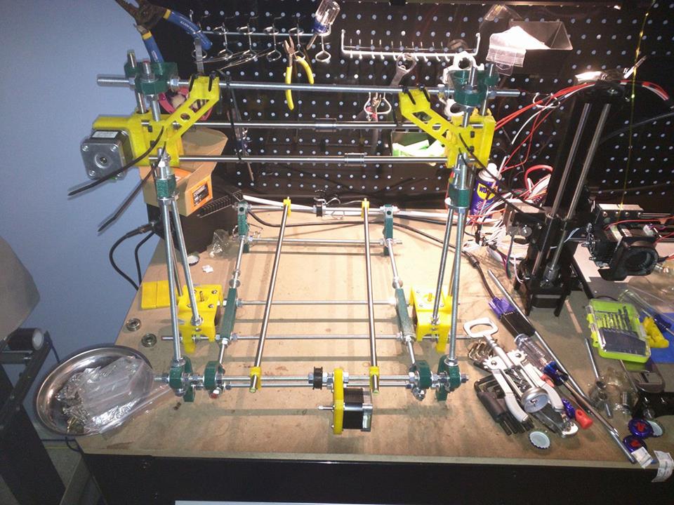
thanks! I saw that m4 note and assumed but wanted to check. It went very well I used m4 bolts I had intended to use for feet long ago .7 hardware and nuts. here's a pic of the hardware and the printer bolted down. I put many rubber feet on the bottom of the wood so the bolt heads wouldn't scratch the table and isolation.


|
Re: RepRap Samuel - A variation on the Mendel March 05, 2017 12:16AM |
Registered: 9 years ago Posts: 42 |
|
Re: RepRap Samuel - A variation on the Mendel March 10, 2017 09:49PM |
Registered: 9 years ago Posts: 32 |
Oh yeah, the wood made a huge difference in the machines shaking. My my z axis threaded rod leadscrews aren't in bearings at the top so they can move around rather than the guild rods since they're also 8mm. They used to slap about in the empty spot where the top 608 bearings should be, now they barely move. 12mm guide rods would probably change the whole calculation in a great way in terms of rigidity. Now strictly speaking whether the machine shakes and whether that shaking effects the process are seperate so I'm not sure it made as big of a difference in the precision of the printer. Although considering the size and weight of mine its also super awesome to move now!
The front supports were a quick way to add rigidity since the front leg things have holes from the original design still in them. I dropped in some threaded rod and it met the top vertices perfectly. there was even room for the clip attachment part to slip on between the angle brackets and the vertical threaded support rods, I didn't even add the screws to the clip since they cant really move anyway. It does suck to lose the i3 look but printing is what counts. The larger problem than height rigidity is that there's only one threaded rod going the length of the machine front to back wise, and there's more to the "front" area so the back can lean forward on it. In theory I think the idea is supposed to be that the guide rods act as that second rod, but in my case at least I 1) prefer to leave one end of one rod loose to allow any error that would jam or screw with movement to flex out (my 12mm rod bed mounts are rigid) and 2) my experience is that the mounts for smooth rod cant ever really grip well enough to resist slip unless maybe you cut a groove in it.
Since I opted to go with a different extruder design than yours ( i think) z height isn't a problem. I forget why now lol but I wanted a slimmer profile to allow clearance in some direction. when I added the front support rods it was nice to not have to worry.
While I was mucking about I figured I'd add one of those bed leveling sensors since my bed is a funhouse mirror level of warped. it's diamond plate alum from lowes, cut by hand and straighten by eye, with a super thin cheapo glass pane from the window repair section of lowes. needless to say bed leveling has been challenging at times. My best method and in truth works really well was to just set z-min height to touching the bed full on, then in some places the first layer was smashed into the bed, others not. It hasn't been a problem on the smashed against the bed areas but adhesion can suck in other areas. I mean it's still workable even at my larger bed size. I was able to print my wife the makerbot headphone stand they have featured around now. its great but large, mostly in the Y axis for most printers. I did a ton of reasearch and settled on a $10 6-36v 1-10mm capacitive NPN sensor with a 18mm diameter from amazon. My reasonong is, since my bed is aluminum with glass over so inductive done simple was not gonna happen, I didn't want any moving parts (That new BTouch probe is great but too $$$), NPN so the signal would be ground and therefore safe for the ramps setup. I found a prefect sensor mount for my extruder on thingiverse. I hooked my sensor to the unused x max endstop signal pin, and 12v of the power supply. in marlin the options for using the probe, without loosing z-min endstop is there. I also choose bi-linear mesh auto bed leveling with a 4x4 grid, double tap probing and the experimental bi-linear subdivision enabled. it's pretty fun to watch it move around and adjust
my_mount.stl
i3extruder.zip
Edited 2 time(s). Last edit at 03/10/2017 09:57PM by mcmasterp.
The front supports were a quick way to add rigidity since the front leg things have holes from the original design still in them. I dropped in some threaded rod and it met the top vertices perfectly. there was even room for the clip attachment part to slip on between the angle brackets and the vertical threaded support rods, I didn't even add the screws to the clip since they cant really move anyway. It does suck to lose the i3 look but printing is what counts. The larger problem than height rigidity is that there's only one threaded rod going the length of the machine front to back wise, and there's more to the "front" area so the back can lean forward on it. In theory I think the idea is supposed to be that the guide rods act as that second rod, but in my case at least I 1) prefer to leave one end of one rod loose to allow any error that would jam or screw with movement to flex out (my 12mm rod bed mounts are rigid) and 2) my experience is that the mounts for smooth rod cant ever really grip well enough to resist slip unless maybe you cut a groove in it.
Since I opted to go with a different extruder design than yours ( i think) z height isn't a problem. I forget why now lol but I wanted a slimmer profile to allow clearance in some direction. when I added the front support rods it was nice to not have to worry.
While I was mucking about I figured I'd add one of those bed leveling sensors since my bed is a funhouse mirror level of warped. it's diamond plate alum from lowes, cut by hand and straighten by eye, with a super thin cheapo glass pane from the window repair section of lowes. needless to say bed leveling has been challenging at times. My best method and in truth works really well was to just set z-min height to touching the bed full on, then in some places the first layer was smashed into the bed, others not. It hasn't been a problem on the smashed against the bed areas but adhesion can suck in other areas. I mean it's still workable even at my larger bed size. I was able to print my wife the makerbot headphone stand they have featured around now. its great but large, mostly in the Y axis for most printers. I did a ton of reasearch and settled on a $10 6-36v 1-10mm capacitive NPN sensor with a 18mm diameter from amazon. My reasonong is, since my bed is aluminum with glass over so inductive done simple was not gonna happen, I didn't want any moving parts (That new BTouch probe is great but too $$$), NPN so the signal would be ground and therefore safe for the ramps setup. I found a prefect sensor mount for my extruder on thingiverse. I hooked my sensor to the unused x max endstop signal pin, and 12v of the power supply. in marlin the options for using the probe, without loosing z-min endstop is there. I also choose bi-linear mesh auto bed leveling with a 4x4 grid, double tap probing and the experimental bi-linear subdivision enabled. it's pretty fun to watch it move around and adjust


my_mount.stl
i3extruder.zip
Edited 2 time(s). Last edit at 03/10/2017 09:57PM by mcmasterp.
|
Re: RepRap Samuel - A variation on the Mendel March 29, 2017 01:42PM |
Registered: 7 years ago Posts: 2 |
I'm in the process of building this and have most of it put together. For the Z axis threaded rod do you guys just put a few nuts in the top and drill for a set screw on the bottom to hold it in place or is there a better way to do this? Also, has anyone experimented with the best bed size? I'm going to reuse a 200x200 platform but it looks like I'm going to have tons of extra space.
|
Re: RepRap Samuel - A variation on the Mendel March 30, 2017 12:51AM |
Registered: 9 years ago Posts: 42 |
Hi Ceefus,
To be honest you have me a bit lost when you ask about a threaded rods with nuts and set screws. I'll assume that you are talking about the z-axis threaded rod that turns to move the height of your extruder. In mu case I am using 6mm rods for z-height, from the pics that I see mcmasterp has 8mm rods. We both have different methods of coupling the rod to the stepper motor. In my case, I printed some couplers (you'll also need a short bit of aquarium air tube on the stepper for good grip) which you will find in the repository for this printer. Mcmasterp is using a set of aluminium couplers that are pretty easily available online. In no case did we drill holes for set screws. On the top, we left out the bearing and do not have any nuts either. The initial design with the bearing was too constrained, so removal of the bearing gave way for better prints. Take a look at the pictures on the fist page of this thread, you should be able to clearly see the different couplers that we used.
Hope that helps!
Edited 1 time(s). Last edit at 03/30/2017 12:52AM by silpstream.
|
Re: RepRap Samuel - A variation on the Mendel March 30, 2017 08:03AM |
Registered: 9 years ago Posts: 32 |
|
Re: RepRap Samuel - A variation on the Mendel April 09, 2017 01:02AM |
Registered: 7 years ago Posts: 2 |
|
Re: RepRap Samuel - A variation on the Mendel April 09, 2017 08:24AM |
Registered: 9 years ago Posts: 32 |
|
Re: RepRap Samuel - A variation on the Mendel May 11, 2017 12:31AM |
Registered: 10 years ago Posts: 10 |
I've had my eye on this thread for a while now and finally finished printing the parts last weekend, so the rebuild is underway! Great design, I'm excited to get it up and running again!
A few questions that I haven't been able to answer from looking at the pictures:
-The y-axis belt holder (under aluminum plate), how is that assembled? I have several different parts available for it but cannot figure out how they go together in a way that both holds the belt in place and acts as a tensioner. Or maybe my belt routing needs some guidance...
-The x-axis belt tensioner uses two 623 bearings, but there is still a lot of room in that space. I've been using a couple of washers to fill the space, but is something else recommended?
-Do you have any recommended values for spacing between the plastic parts along the rods?
Thanks! I can't wait to get this done!
Edited 1 time(s). Last edit at 05/11/2017 12:48AM by rcrummett.
|
Re: RepRap Samuel - A variation on the Mendel May 11, 2017 12:42PM |
Registered: 9 years ago Posts: 42 |
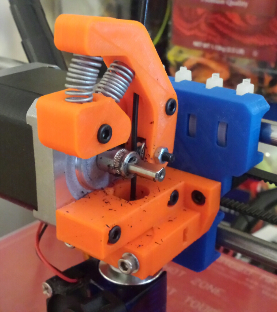
I've attached some pictures here. Hopefully you'll be able to figure out what I did.
For the x axis pull, there is actually a spacer part "sam_x-end-pulley-spacer.stl" that can be printed if you do no want to use the washers. Also there is "sam_x-end-pulley.stl" which I labeled as do not print, but can be used if you want. I did use it, but I've seen builds without it. Mileage varies for this part and depending on how smooth your print is, you could be better off using just the bearings. I had to use CA glue to fuse the two parts together with the bearings inside, after which I sanded everything smooth.
Good luck!
|
Re: RepRap Samuel - A variation on the Mendel May 11, 2017 07:43PM |
Registered: 10 years ago Posts: 10 |
|
Re: RepRap Samuel - A variation on the Mendel May 20, 2017 10:33PM |
Registered: 10 years ago Posts: 10 |
Finished building last night and testing right now. Initial results not good...I'm putting out way too much plastic. Guess in my excitement I forgot to recalibrate the extruder...
I'm also getting a lot of filament grinding and it has me wondering if I have too much tension on my extruder. I'm using the "default" extruder, so I'm wondering; what are other people using for springs?
I'm also getting a lot of filament grinding and it has me wondering if I have too much tension on my extruder. I'm using the "default" extruder, so I'm wondering; what are other people using for springs?
|
Re: RepRap Samuel - A variation on the Mendel May 21, 2017 04:50AM |
Registered: 9 years ago Posts: 42 |
LOL... calibration of the extruder is definitely needed. You may find your grinding stops once everything is calibrated cause you won't be pushing as much plastic through.
Anyhow, could you send a pic of your setup? Also what diameter filament are you using and what drive gear? Normally the spring only causes a problem when there is lack of tension. Either way a good pic would help.
Anyhow, could you send a pic of your setup? Also what diameter filament are you using and what drive gear? Normally the spring only causes a problem when there is lack of tension. Either way a good pic would help.
|
Re: RepRap Samuel - A variation on the Mendel May 21, 2017 02:34PM |
Registered: 10 years ago Posts: 10 |
I'm using 1.75mm filament with a Haobase drive gear (found on Amazon, 7mm effective diameter)
UPDATE: I think I've figured this out now. I was using a Greg's hinged extruder with the 43-tooth gear and the 10-tooth gear, which according to Triffid Hunter's calibration guide should provide an E value around 625. Looking at the formula used to calculate the E value and dividing be 4.3 (43/10 - this value is no longer a part of our path) gives an E value around 145. I've currently got mine at 155 and it seems to be working better. It just seemed a little surprising to be so low compared to where I was at before, but it makes sense now!
Edited 2 time(s). Last edit at 05/21/2017 11:46PM by rcrummett.
|
Re: RepRap Samuel - A variation on the Mendel July 11, 2017 07:54PM |
Registered: 10 years ago Posts: 651 |
Redesigned the X Idler on mine again. It was just too thin and was bending/cracking preventing proper tensioning. I also added cones so that a machined GT2 pulley could be used. https://www.thingiverse.com/thing:2430524
|
Re: RepRap Samuel - A variation on the Mendel September 05, 2017 12:56PM |
Registered: 11 years ago Posts: 18 |
Starting to print out these parts to upgrade and reuse vitamins from my old I2. I see that i can reuse
the y motor mount.
My question is (at this time) about the vertex pieces. I see 3 sets of 2 vertexes but I am
unsure which are front or rear and inside or outside in the rear Can I reuse old ones from my I2?)
I'm a little timid about the reuse of parts because once I tear down my old machine I am stuck.
I appreciate any and all help....
|
Re: RepRap Samuel - A variation on the Mendel September 05, 2017 01:19PM |
Registered: 9 years ago Posts: 42 |
The vertex named "third_party/prusa-leveling-vertex-M8-M4.stl" in the wiki can be replaced with the vertex from the i2. These belong to the front of the machine.
"sam_20deg-vertex-L/R" and "sam_vertex-L/R" should be printed new.
However if you want to be able to add on the adjustable levelling feet ("sam_leveling-foot.stl") you will need to reprint all the vertexes.
Hope that helps. Good luck!
"sam_20deg-vertex-L/R" and "sam_vertex-L/R" should be printed new.
However if you want to be able to add on the adjustable levelling feet ("sam_leveling-foot.stl") you will need to reprint all the vertexes.
Hope that helps. Good luck!
|
Re: RepRap Samuel - A variation on the Mendel September 05, 2017 01:27PM |
Registered: 11 years ago Posts: 18 |
|
Re: RepRap Samuel - A variation on the Mendel September 05, 2017 02:08PM |
Registered: 9 years ago Posts: 32 |
So funny what a coincidence things are. I just pulled out my old i2 that had never worked well due to hotend heat issues and started printing the Samuel parts yesterday. I have no idea what I'll do with an extra printer but I guess the answer is print more lol. Just wanted to post and thank slipstream once again for the gift that keeps on giving!
|
Re: RepRap Samuel - A variation on the Mendel September 05, 2017 03:03PM |
Registered: 9 years ago Posts: 42 |


Sorry, only registered users may post in this forum.