Dual Z drivers setup in firmware
Posted by cojarbi
|
Dual Z drivers setup in firmware November 18, 2015 01:12AM |
Registered: 8 years ago Posts: 18 |
I'm having a hard time getting this to work on either Marlin or repeiter. Bough give me the same problem.
I'm using a Megatronics v2 board and attaching Z2 to E2. On everything I try Z2 only move in one direction.
I have read that I'm supposed to change the pins on the pins. He but have tried many ways without getting it to work.
Any help is appreciated
I'm using a Megatronics v2 board and attaching Z2 to E2. On everything I try Z2 only move in one direction.
I have read that I'm supposed to change the pins on the pins. He but have tried many ways without getting it to work.
Any help is appreciated
|
Re: Dual Z drivers setup in firmware November 18, 2015 03:54AM |
Registered: 8 years ago Posts: 5,232 |
It seems the "dir"-pin of Z2/E2 isn't responding.
It can be a hardware problem, but more likely it isn't configured right in pins.h
Do you have a pinmap of the megatronics board?
Alternatively, you can usually run two stepper motors in series with only the Z1 driver.
-Olaf
Edited 1 time(s). Last edit at 11/18/2015 03:55AM by o_lampe.
It can be a hardware problem, but more likely it isn't configured right in pins.h
Do you have a pinmap of the megatronics board?
Alternatively, you can usually run two stepper motors in series with only the Z1 driver.
-Olaf
Edited 1 time(s). Last edit at 11/18/2015 03:55AM by o_lampe.
|
Re: Dual Z drivers setup in firmware November 18, 2015 07:49AM |
Registered: 8 years ago Posts: 18 |
Olaf
Is this it:
#define ORIG_X_STEP_PIN 26
#define ORIG_X_DIR_PIN 27
#define ORIG_X_ENABLE_PIN 25
#define ORIG_X_MIN_PIN 37
#define ORIG_X_MAX_PIN 40 //2 //Max endstops default to disabled "-1", set to commented value to enable.
#define ORIG_Y_STEP_PIN 4 // A6
#define ORIG_Y_DIR_PIN 54 // A0
#define ORIG_Y_ENABLE_PIN 5
#define ORIG_Y_MIN_PIN 41
#define ORIG_Y_MAX_PIN 38 //15
#define ORIG_Z_STEP_PIN 56 // A2
#define ORIG_Z_DIR_PIN 60 // A6
#define ORIG_Z_ENABLE_PIN 55 // A1
#define ORIG_Z_MIN_PIN 18
#define ORIG_Z_MAX_PIN 19
#define ORIG_E0_STEP_PIN 35
#define ORIG_E0_DIR_PIN 36
#define ORIG_E0_ENABLE_PIN 34
#define ORIG_E1_STEP_PIN 29
#define ORIG_E1_DIR_PIN 39
#define ORIG_E1_ENABLE_PIN 28
#define ORIG_E2_STEP_PIN 23
#define ORIG_E2_DIR_PIN 24
#define ORIG_E2_ENABLE_PIN 22
If not then I dont have it. And I'm not sure what I'm looking for.
I don't think it's hardware since I have tried using the other extruders as Z2 and the same permits.
Can you tell me what exactly I'm looking for?
|
Re: Dual Z drivers setup in firmware November 18, 2015 03:19PM |
Registered: 14 years ago Posts: 128 |
May pay to double check the following in Marlin.
I am using a Ramps board and using dual steppers. Also have dual Zmin end stops and one ZMax stops which allow both of the two steppers to home if they get out of sync. Had to change some of marlin code to get it working.
Note: As below you should be able to see that defining Z_DUAL_STEPPER_DRIVERS then sets the E2 driver signals to the Z2 driver signals and if the Marlin E2 Pins are setup correctly for your board then it should work.
If not you could try changing Marlin Pins definition to have the E2 pins to your E1pin to test if its a wiring/board issue.
Configuration.adv.h
Line 129
#define Z_DUAL_STEPPER_DRIVERS
#ifdef Z_DUAL_STEPPER_DRIVERS
// Z_DUAL_ENDSTOPS is a feature to enable the use of 2 endstops for both Z steppers - Let's call them Z stepper and Z2 stepper.
// That way the machine is capable to align the bed during home, since both Z steppers are homed.
// There is also an implementation of M666 (software endstops adjustment) to this feature.
// After Z homing, this adjustment is applied to just one of the steppers in order to align the bed.
// One just need to home the Z axis and measure the distance difference between both Z axis and apply the math: Z adjust = Z - Z2.
// If the Z stepper axis is closer to the bed, the measure Z > Z2 (yes, it is.. think about it) and the Z adjust would be positive.
// Play a little bit with small adjustments (0.5mm) and check the behaviour.
// The M119 (endstops report) will start reporting the Z2 Endstop as well.
#define Z_DUAL_ENDSTOPS
#ifdef Z_DUAL_ENDSTOPS
#define Z2_STEP_PIN E2_STEP_PIN // Stepper to be used to Z2 axis.
#define Z2_DIR_PIN E2_DIR_PIN
#define Z2_ENABLE_PIN E2_ENABLE_PIN
#define Z2_MAX_PIN 36 //Endstop used for Z2 axis. In this case I'm using XMAX in a Rumba Board (pin 36)
const bool Z2_MAX_ENDSTOP_INVERTING = false;
#define DISABLE_XMAX_ENDSTOP //Better to disable the XMAX to avoid conflict. Just rename "XMAX_ENDSTOP" by the endstop you are using for Z2 axis.
#endif
#endif // Z_DUAL_STEPPER_DRIVERS
Cheers Bruce
|
Re: Dual Z drivers setup in firmware November 18, 2015 08:35PM |
Registered: 8 years ago Posts: 18 |
Bruce
Thanks for the info. Still unclear on many things. First I have set Z dual in Marlin configuration.h but what you suggest does not appear when I change that.
Do I need to change something in pins.h? I've being searching for the pinout of my Megatronics board.
I appreciate the help but could you be more specific?
|
Re: Dual Z drivers setup in firmware November 19, 2015 03:33PM |
Registered: 14 years ago Posts: 128 |
Not sure which version of Marlin you are using... Later versions you set up dual Z in Configuration.adv.h
I am not totally sure how the Megatronics board is wired to know which pins are wired to the stepper driver..
With the Ramps board I am using, there are only 5 stepper drivers, normally 3 for XYZ axis and 2 for extruders (E0 & E1).
What happens you use the second extruder for the second Z axis, thus you can only have one extruder.
I have the Z2 pins setup ( Dir/step/enable) set the same as the E1.
Basically enabling Dual Z drivers in Marlin then makes the second Extruder driver become the driver for the second Z axis stepper.
The Megatronics board looks to have 6 stepper drivers, 3 for XYZ axis and 3 for extruders.
Thus you will still be using one of the extruders drivers to become your second Z axis driver.
Thus the Pin setup (Dir/step/enable) for the second Z Axis Z2 ( Pins.h) will need be set the same as your second extruder(E1)
Hopefully I have got that right.
|
Re: Dual Z drivers setup in firmware November 19, 2015 04:26PM |
Registered: 8 years ago Posts: 18 |
RepRop
I have setup either Marlin and Repetier to solve this and bough are giving me the same issue.
The second Z only moves in one direction.
What I have done in pins.h is use the same numbers from Z1 on E2. Off course I have enabled Dual Z in configuration.h. I cannot find any other way fix this. I have searched like crazy.
|
Re: Dual Z drivers setup in firmware November 20, 2015 03:37AM |
Registered: 8 years ago Posts: 5,232 |
|
Re: Dual Z drivers setup in firmware November 20, 2015 07:15AM |
Registered: 8 years ago Posts: 18 |
|
Re: Dual Z drivers setup in firmware November 20, 2015 07:31AM |
Registered: 10 years ago Posts: 444 |
|
Re: Dual Z drivers setup in firmware November 20, 2015 05:53PM |
Registered: 14 years ago Posts: 128 |
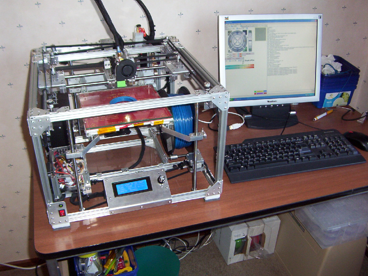
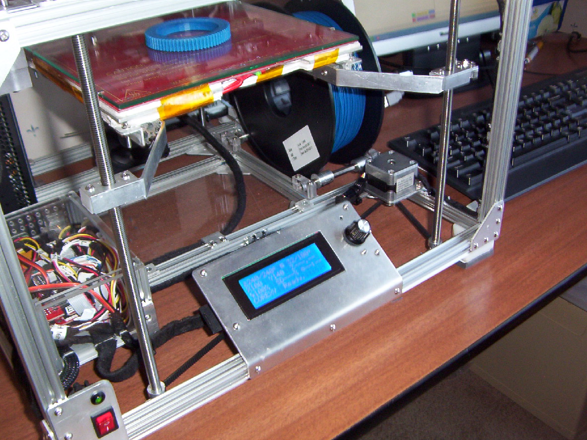
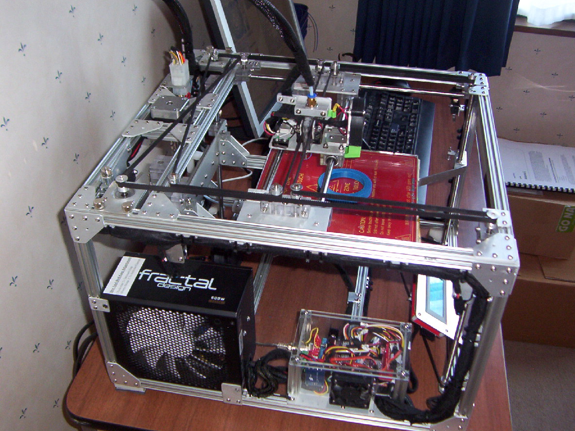
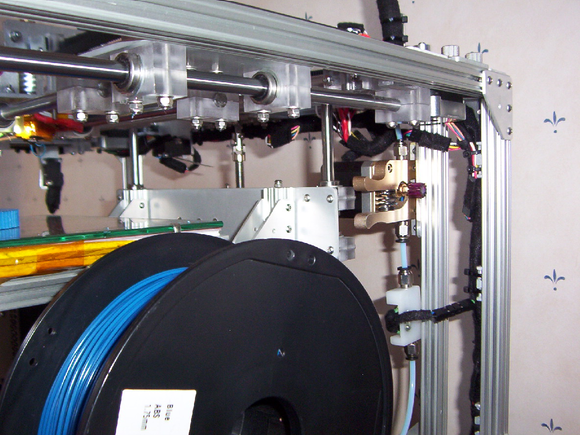
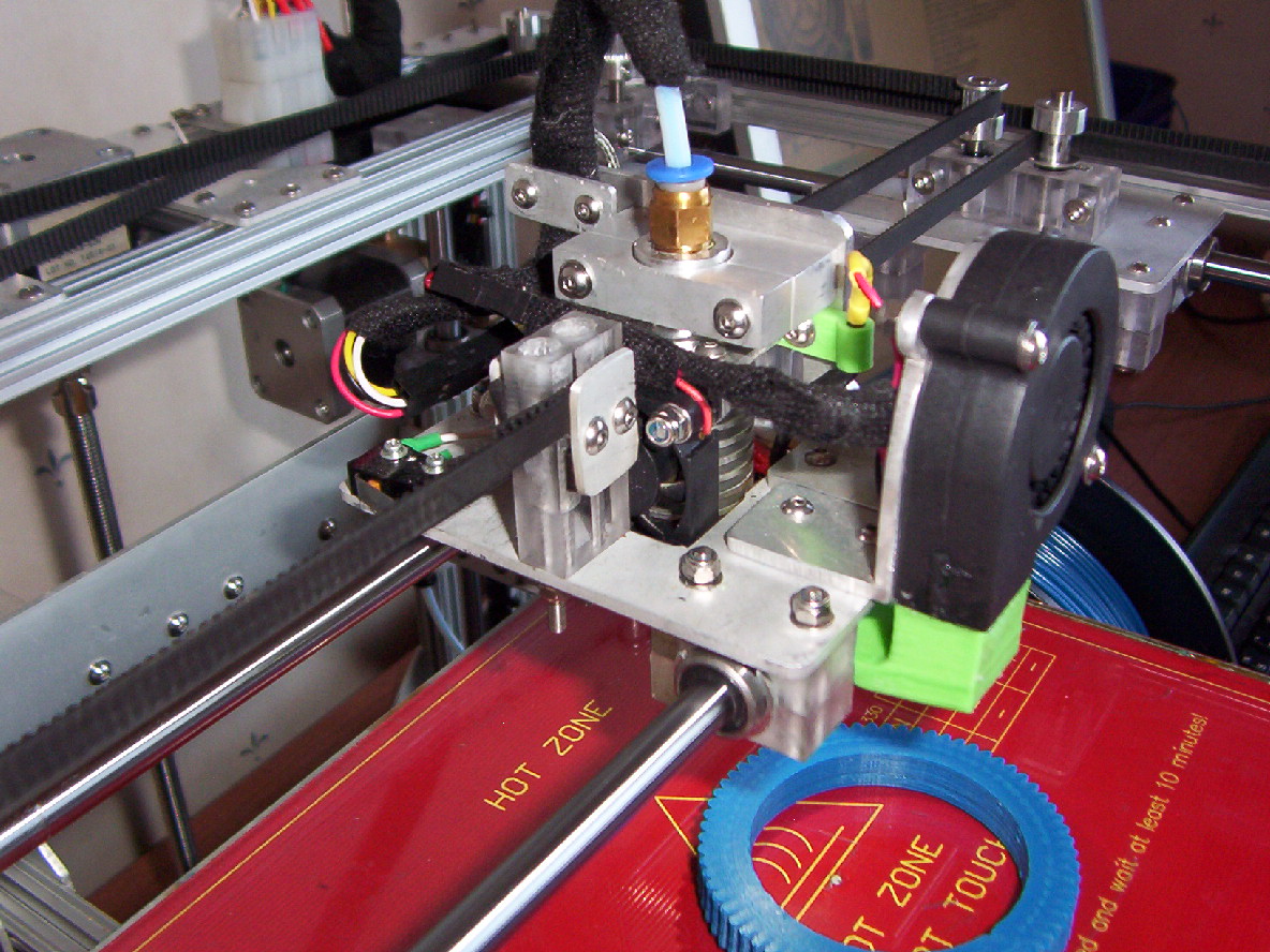
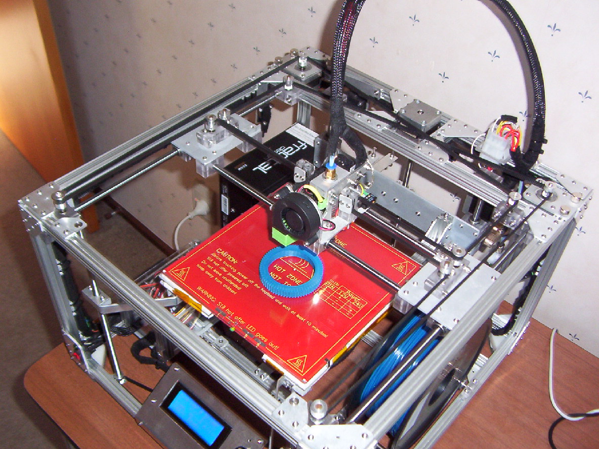
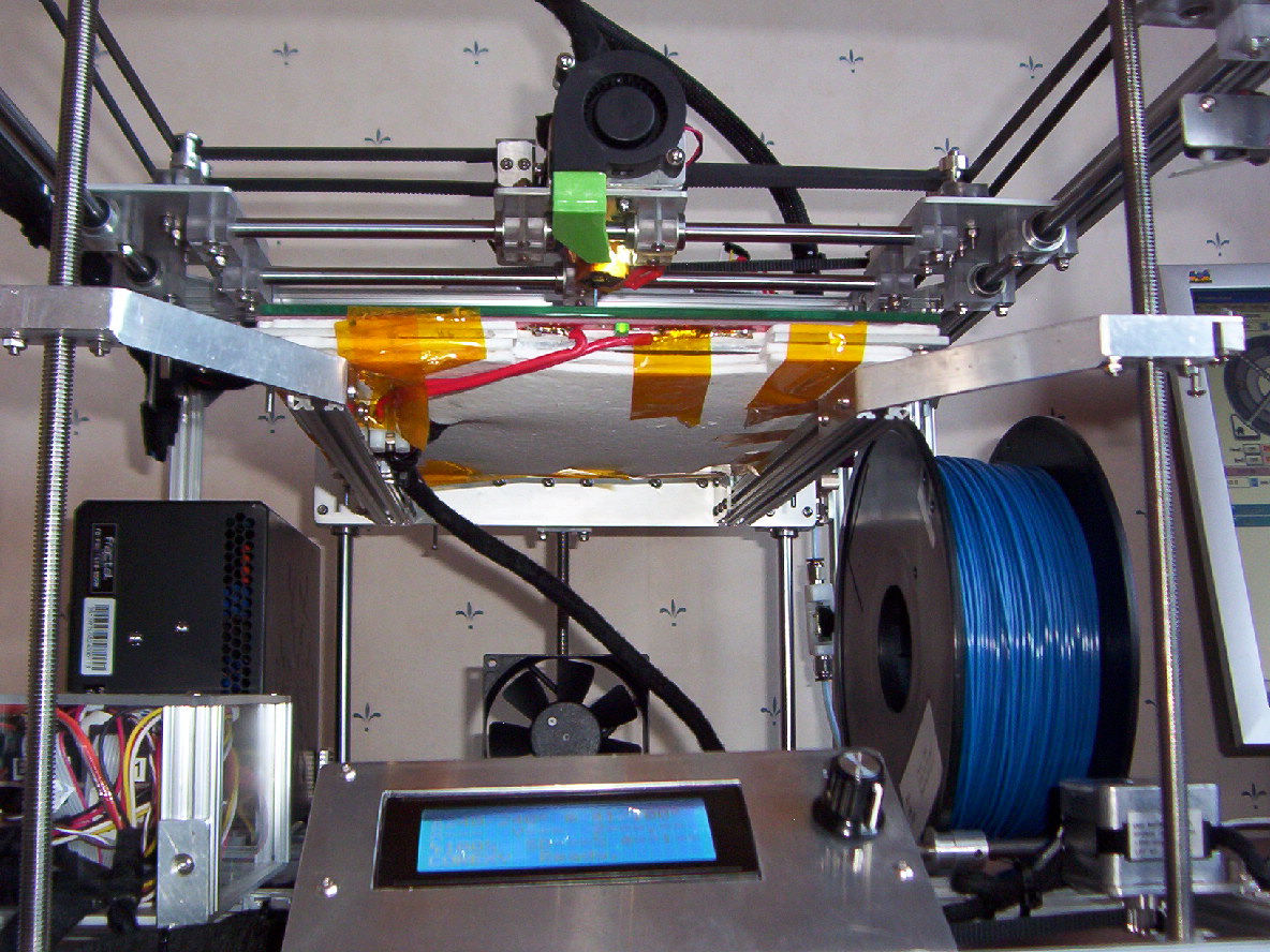
A few pictures of my CoreXY machine that uses dual z steppers with 3 lead screws.
Using 7 ends stops - Xmin, Xmax, Ymin, Ymax, Zmin , Z2 min, Z max.
Auto syncs the two stepper motors when homing z axis.
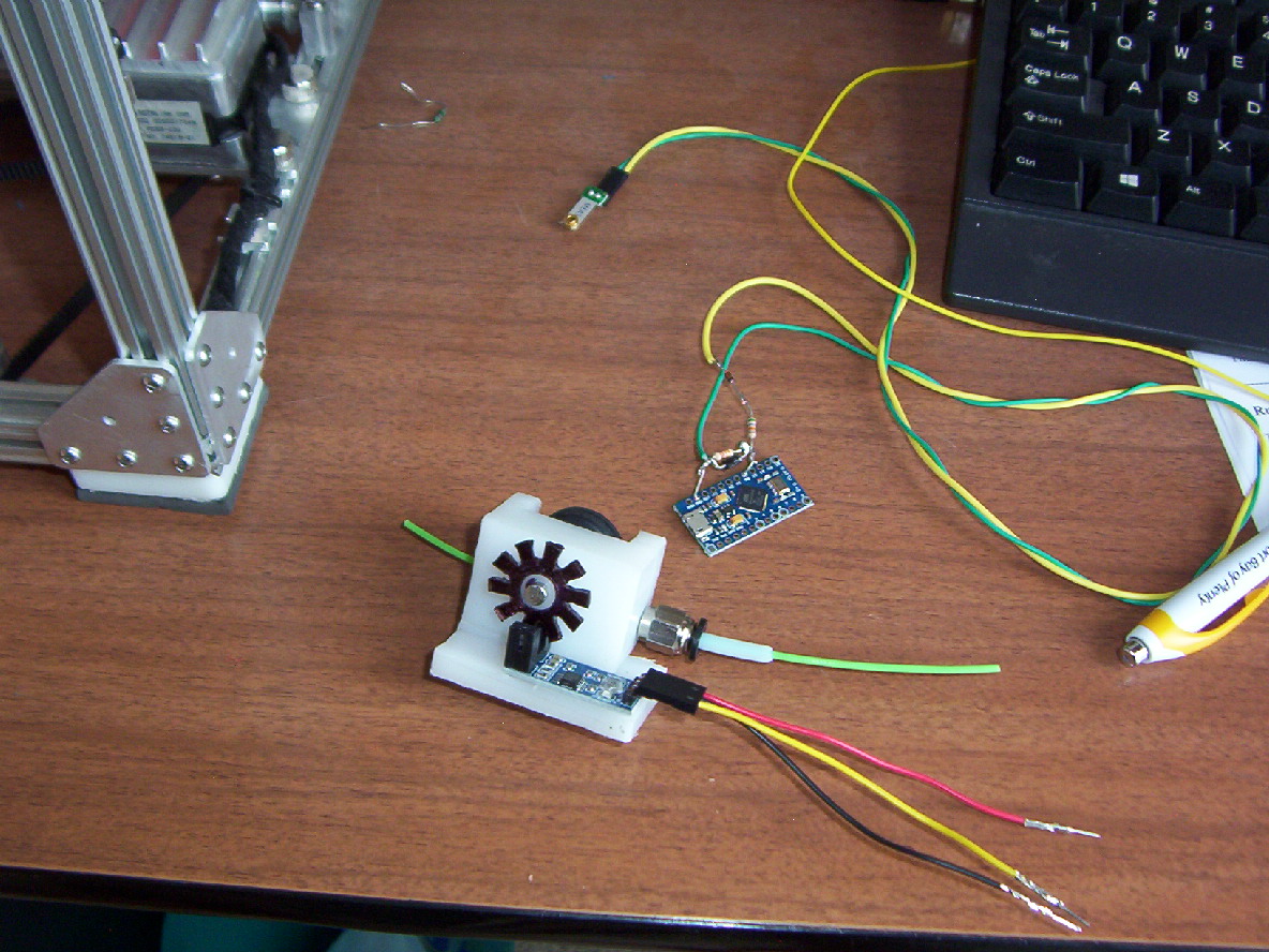
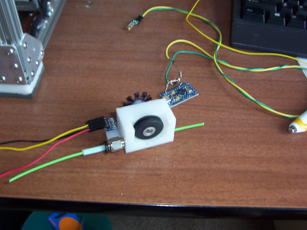
Just working on making a assembly that will monitor that the filament is moving or runs out.
The assembly will generate pulses when the filament is moving, Need to modify Marlin to output a dual extruder stepper pulse to another I/O pin.
I will then will have an Arduino Leonardo Mini pro processor monitor the extruder step pulses and filament pulses, if there is no pulses when having extruder stepper pulses it will then activate the filament-out I/O line which will halt the printer.
The filament out function is already in Marlin when printing from SD card. Need to check out how it works when printing from PC.
Using 7 ends stops - Xmin, Xmax, Ymin, Ymax, Zmin , Z2 min, Z max.
Auto syncs the two stepper motors when homing z axis.
Just working on making a assembly that will monitor that the filament is moving or runs out.
The assembly will generate pulses when the filament is moving, Need to modify Marlin to output a dual extruder stepper pulse to another I/O pin.
I will then will have an Arduino Leonardo Mini pro processor monitor the extruder step pulses and filament pulses, if there is no pulses when having extruder stepper pulses it will then activate the filament-out I/O line which will halt the printer.
The filament out function is already in Marlin when printing from SD card. Need to check out how it works when printing from PC.
Attachments:
open | download - CoreXY-1.JPG (340 KB)
open | download - CoreXY-2.JPG (332.6 KB)
open | download - CoreXY-6.JPG (316.8 KB)
open | download - CoreXY-5.JPG (336.3 KB)
open | download - CoreXY-3.JPG (292.6 KB)
open | download - CoreXY-4.JPG (333.2 KB)
open | download - CoreXY-7.JPG (331.3 KB)
open | download - CoreXY-8.JPG (320.4 KB)
open | download - 000_2795.JPG (344.7 KB)
open | download - 000_2796.JPG (342.5 KB)
|
Re: Dual Z drivers setup in firmware November 20, 2015 06:22PM |
Registered: 8 years ago Posts: 18 |
|
Re: Dual Z drivers setup in firmware November 20, 2015 08:04PM |
Registered: 14 years ago Posts: 128 |
Have attached a copy of my Marlin firmware setting.
Also some info of the changes I have done with Marlin to get auto syncing of the two Z axis stepping motors/ LCD menu's and filament out.
Cheers
Also some info of the changes I have done with Marlin to get auto syncing of the two Z axis stepping motors/ LCD menu's and filament out.
Cheers
|
Re: Dual Z drivers setup in firmware November 21, 2015 12:26AM |
Registered: 8 years ago Posts: 18 |
As i wantred to move forward i decided in the meantime to connect bough Z to the same driver, its not working perfectly but its a start. The i went to test the extruder. Gues whats. It only moves on one direction.
So:
- Changed Drivers, same thing
- changed stepper, same thing
- changed firmware, same thing
- changed cable orientation, changed direction but only one way still
There must be something im missing here
So:
- Changed Drivers, same thing
- changed stepper, same thing
- changed firmware, same thing
- changed cable orientation, changed direction but only one way still
There must be something im missing here
|
Re: Dual Z drivers setup in firmware November 21, 2015 06:28PM |
Registered: 14 years ago Posts: 128 |
Hi,
Just had a look at the Megatronics v2 board circuit - the E0 Extruder stepper driver uses -
D36 for Direction
D35 for Step
D34 for Enable
If you have these pins set correctly in Marlin (pins.megatronics_2.)h for your extruder E0 then you should expect to have the extruder move in both directions. With movement indicates that you have Step and Enable pins correct.
Failure to have both directions working , you would expect that there could be a fault with the stepper driver. But as you have changed the driver, I would then expect that there is an issue with the DIR signal that comes from the Amega processor to the driver chip assembly.
There also appears to be a connector called E0 Out which shouldn't have anything attached to it. (It provides an output for the processor signal of EO Step/Dir/Enable as well as going to the driver chip assy). A jumper here could short DIR to Gnd.
I would suspect that there could be a solder short between DIR signal PCB trace and ground or that the processor can't toggle the DIR signal on your Megatronics v2 board.
If you download a copy of the Megatronics v2 board and circuit you should be able to see what I am talking about.
If you do in fact have a faulty processor E0 DIR signal you could change to make E1 your extruder driver by setting Marlin E0 to the following and connecting the Extruder stepper to E1 Motor connection (Note: Only change stepper motors when power is off)
D39 for Direction
D29 for Step
D28 for Enable
Basically Marlin will then send extruder 0 signals to the above processor outputs which are connected to E1 extruder driver, this will move the extruder stepper that is connected to the E1 driver connector.
Hope this helps sort your issue out.
Cheers.
|
Re: Dual Z drivers setup in firmware September 25, 2017 08:17AM |
Registered: 7 years ago Posts: 3 |
Good Morning:
I issue I have found in the new versions of Marlin is there is no definition for the Z2_pins. Depending on wich board you are using you need to copy and rename your E1 extruder pins for Z2.
In the pins,h file you will find
#define _X2_PINS
#define _Y2_PINS
#define _Z2_PINS
with no definitions. I am using a Ramps 1.4. I went into pins_RAMPS.h and copied the E1 Extruder settings into pins.h and changed E1 to Z2
//
// Dual X-carriage, Dual Y, Dual Z support
//
#define _X2_PINS
#define _Y2_PINS
#define _Z2_PINS
#define Z2_STEP_PIN 36
#define Z2_DIR_PIN 34
#define Z2_ENABLE_PIN 30
#define Z2_CS_PIN 44
Dual Z_Axis control is now working fine. The older versions used to define the X2, Y2 and Z2 in the pins.h file. with the new pin files there is no definitions for the X2, Y2 or Z2 STEP PINS.
I hopes this helps some of you.
Sorry, only registered users may post in this forum.