Lead Screw usage for X and Y axes
Posted by tobben
|
Anonymous User
Re: Lead Screw usage for X and Y axes March 04, 2016 12:16PM |
Quote
tobben
We're spoiled
But shouldn't a few cleverly coupled components like coils, capacitors and a resistors be able to give a normal a4988 the slight phase shift it needs, just around the resonant frequencies?
I would expect the total cost of the needed component to be < $10. Manually adjusting a potentiometer to adjust a filter to hit the right frequency bandwidth for my setup would be a low additional cost.
Just need a young clever engineer to couple all these together isn't ? Better yet, all done in software.

|
Anonymous User
Re: Lead Screw usage for X and Y axes March 04, 2016 12:20PM |
Quote
the_digital_dentist
I see at least one motor mounted in printed plastic. I hope it isn't PLA- the heat from the motor is going to soften the plastic and cause no end of problems.
I recently replaced a printed ABS motor mount from my printer with an aluminum part. When I looked at the plastic, I found that screw holes had distorted due to heat and tension from the belt. If that happens to ABS, PLA is going to be a disaster.

These printers reproduce themselves but then, they have to die too isn't ?
|
Re: Lead Screw usage for X and Y axes March 04, 2016 02:03PM |
Admin Registered: 17 years ago Posts: 7,879 |
Strange ABS you have there or a very hot motor. My ABS parts go brown and brittle and perhaps crack when they are in a prolonged hot environment (i.e. 65-70C for several years) but they don't soften and distort.
@tobben,
No you can't do it with a few passives. It is generally done with a DSP nowadays that looks at the chopper waveform to infer the back EMF from the motor and calculate its lag and adjust the step timing to cancel oscillation.
[www.hydraraptor.blogspot.com]
@tobben,
No you can't do it with a few passives. It is generally done with a DSP nowadays that looks at the chopper waveform to infer the back EMF from the motor and calculate its lag and adjust the step timing to cancel oscillation.
[www.hydraraptor.blogspot.com]
|
Re: Lead Screw usage for X and Y axes March 04, 2016 03:46PM |
Registered: 8 years ago Posts: 310 |
@the_digital_dentist
I been using pla on the X axis of my i3 with leadscrew thread printed together and my i3 has an enclosure, I been using it for months and not a tiny bit of deforming. You must have a seriously hot motor. I have a thread here from when I first started using pla x idler and motor mount with leadscrew thread printed. You can see how long I been using it. Not a slight bit of problem and my x motor has been going fairly fast and very warm.
Also my i3 hotend holder and fan duct as well as x carriage are made with PET which has the same melting point as pla, again, been using them longer than the leadscrew Threaded x motor and idler, not a tiny bit of deforming.
Edited 1 time(s). Last edit at 03/04/2016 03:49PM by deaconfrost.
|
Re: Lead Screw usage for X and Y axes March 04, 2016 04:31PM |
Registered: 11 years ago Posts: 5,780 |
The motor runs pretty warm, and the enclosure gets to about 45C. It's been running that way for about a year. I have never measured the temperature of the motor.
Ultra MegaMax Dominator 3D printer: [drmrehorst.blogspot.com]
Ultra MegaMax Dominator 3D printer: [drmrehorst.blogspot.com]
|
Re: Lead Screw usage for X and Y axes March 04, 2016 10:25PM |
Admin Registered: 17 years ago Posts: 7,879 |
My motors run at ambient plus 20C and I have them in a 45C chamber, so they get to 65C but ABS doesn't soften till about 90C - 100C. I have a machine about 5 years old like that and the motor brackets have gone yellow but not deformed.
I have had extruder brackets go brown due to rising heat from the hot end but they still don't deform but tend to crack eventually. I insulate the heater block to fix that.
The only brackets I have had deform have been PLA. That creeps at room temperature and goes soft at 55C. I haven't printed PET but although that might have the same melting point as PLA it doesn't have the low glass transition that is the problem.
Are you sure that yellow print is ABS?
[www.hydraraptor.blogspot.com]
|
Re: Lead Screw usage for X and Y axes March 05, 2016 08:37AM |
Registered: 11 years ago Posts: 5,780 |
Yes, 100% sure it is ABS. I think my motor runs hotter than ambient +20C. Maybe the screws caused the distortion. It doesn't matter- I've replaced it with aluminum, something I intended to do from the beginning and finally got around to doing.
Ultra MegaMax Dominator 3D printer: [drmrehorst.blogspot.com]
Ultra MegaMax Dominator 3D printer: [drmrehorst.blogspot.com]
|
Re: Lead Screw usage for X and Y axes March 05, 2016 10:10AM |
Registered: 8 years ago Posts: 310 |
|
Re: Lead Screw usage for X and Y axes March 05, 2016 10:13AM |
Registered: 8 years ago Posts: 310 |
Quote
tobben
Quote
deaconfrost
As it is the printer tops out at around 25mm/s to 30mm/s I don't think it go any faster with 1 start.
Is it mid-band resonance that limits the speed? (would look like these videos: [1], [2], [3]).
BTW, found a video showing anti-resonant drivers + rotating the nut: [4] The cheapest anti-resonance stepper drivers I've found are $40 each [5]. This makes cheap leadscrew + anti-resonance driver a cheaper option than branded aggressive leadscrew + cheap driver. Still not cheap though...
I wonder why anti-resonance drivers are so expensive? The problem of resonance seems easy enough to understand (mass/spring system [6], [7]) and the solution of electronic damping seems simple enough to implement at home [8].
yea thats partly the problem, I'll be swapping the leadscrew out for 4 or 6 starts soon, that shall be exciting
first test single start leadscrew on x y axis
bare in mind I've designed this with only 3 months experience with 3d printers so go easy on me how bad you might think it is
Edited 1 time(s). Last edit at 03/05/2016 10:14AM by deaconfrost.
|
Re: Lead Screw usage for X and Y axes March 05, 2016 10:56AM |
Registered: 11 years ago Posts: 5,780 |
That looks like it is running well. It will be interesting to see if the frame is rigid enough once you get things moving faster.
Ultra MegaMax Dominator 3D printer: [drmrehorst.blogspot.com]
Ultra MegaMax Dominator 3D printer: [drmrehorst.blogspot.com]
|
Re: Lead Screw usage for X and Y axes March 05, 2016 10:59AM |
Registered: 8 years ago Posts: 310 |
|
Re: Lead Screw usage for X and Y axes March 05, 2016 04:00PM |
Registered: 10 years ago Posts: 401 |
Looking good!
How thick are the lead screws? And do you use anti-backlash nuts? I noticed you use only one smooth rod, so you're relying on straightness of the lead screw.
torbjornludvigsen.com
How thick are the lead screws? And do you use anti-backlash nuts? I noticed you use only one smooth rod, so you're relying on straightness of the lead screw.
torbjornludvigsen.com
|
Re: Lead Screw usage for X and Y axes March 05, 2016 06:24PM |
Registered: 8 years ago Posts: 310 |
they're 10mm and smooth rods are 12mm, before I put the leadscrew on there was no hanging, and I try to twist them gently, they didnt move at all, so should be strong enough I hope
I am plaining on using another brass nut on the other end of them with springs in between them for anti back lash, but since I change the leadscrew, Im going to use different approach, I keep you updated
Edited 1 time(s). Last edit at 03/05/2016 06:25PM by deaconfrost.
I am plaining on using another brass nut on the other end of them with springs in between them for anti back lash, but since I change the leadscrew, Im going to use different approach, I keep you updated
Edited 1 time(s). Last edit at 03/05/2016 06:25PM by deaconfrost.
|
Anonymous User
Re: Lead Screw usage for X and Y axes March 06, 2016 01:30PM |
|
Re: Lead Screw usage for X and Y axes March 07, 2016 06:55PM |
Registered: 8 years ago Posts: 310 |
|
Anonymous User
Re: Lead Screw usage for X and Y axes March 08, 2016 01:58AM |
Quote
deaconfrost
Quote
MKSA
Quote
deaconfrost
Yea I should find that out in couple weeks, have 4 start leadscrew ordered
From what I see, when one axis moves, the other axis carriage is moving too with the head isn't ?
sorry but I don't get what you asking
When the X motor turns the X lead screw, does the Y motor+Y screw+guide, in short the Y ass'y+head moves ?
And when the Y motor turns the Y lead screw, does the X motor+ X screw+guide, in short the X ass's+head moves ?
Edited 1 time(s). Last edit at 03/08/2016 02:00AM by MKSA.
|
Re: Lead Screw usage for X and Y axes March 08, 2016 08:27PM |
Registered: 8 years ago Posts: 310 |
|
Anonymous User
Re: Lead Screw usage for X and Y axes March 09, 2016 03:50AM |
OK, I was right then. The issue you have here is the added weight. An other point, the flexible couplers, they act as a spring.
Personally, the key factor is to minimize the mass to be moved, ideally just a hotend printhead in X, Y. It is why I like the Ultimaker approach, which origin can be found in old days plotter BTW. Why not belt for X, Y ? The GT2 profile is quite good, limited backlash, low mass and provide adequate positional accuracy. I was thinking about dyneema thread too. Of course for Z, a T leadscrew with a composite nut, no real need for antibacklash, slow movement, non reverse even with 8mm lead.
Personally, the key factor is to minimize the mass to be moved, ideally just a hotend printhead in X, Y. It is why I like the Ultimaker approach, which origin can be found in old days plotter BTW. Why not belt for X, Y ? The GT2 profile is quite good, limited backlash, low mass and provide adequate positional accuracy. I was thinking about dyneema thread too. Of course for Z, a T leadscrew with a composite nut, no real need for antibacklash, slow movement, non reverse even with 8mm lead.
|
Re: Lead Screw usage for X and Y axes March 09, 2016 07:41AM |
Registered: 8 years ago Posts: 310 |
|
Re: Lead Screw usage for X and Y axes March 09, 2016 12:30PM |
Registered: 8 years ago Posts: 1,671 |
My second printer thats currently rising from a bag of bits, has the option for driving Y with leadscrew(8mm x4) and also the X, as long as it could work at 50mm speed I think I could be happy with that, but will have to see if it presents any issues, mainly wobble from the screw turning, I like the idea of only rotating the nut, but not sure how to implement. the motor would have to be on the carriage near nut...plus other stuff bearings n things... I've also been toying with the idea of dyneema attached to a nut on a lead screw, which could pull the line as nut moves...but not sure if it would help or hinder things at the moment.
|
Re: Lead Screw usage for X and Y axes April 21, 2016 11:43AM |
Registered: 8 years ago Posts: 10 |
|
Re: Lead Screw usage for X and Y axes April 21, 2016 11:59AM |
Registered: 10 years ago Posts: 401 |
Hi albatroopa! Sorry for not updating this thread, I'm writing my Master's =)
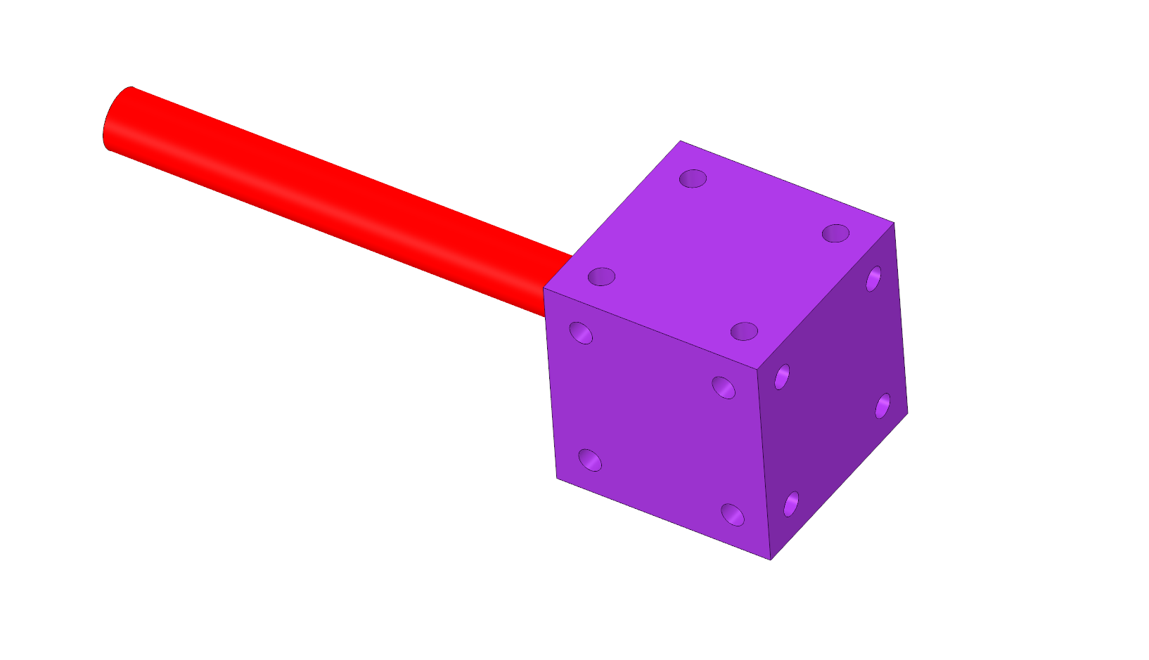
Here's a little prototype I built last week, just to see how simplistic linear actuators inspired by deaconfrost's printer would look like:
I'm aiming for extreme ease of build, teach and usage because the Master's is about designing an assembly workshops. Here's my latest sketch of how to deal with alignment:
I'd like to measure the need for thrust bearings when I get the time...
torbjornludvigsen.com
Here's a little prototype I built last week, just to see how simplistic linear actuators inspired by deaconfrost's printer would look like:

I'm aiming for extreme ease of build, teach and usage because the Master's is about designing an assembly workshops. Here's my latest sketch of how to deal with alignment:

I'd like to measure the need for thrust bearings when I get the time...
torbjornludvigsen.com
|
Re: Lead Screw usage for X and Y axes April 21, 2016 12:41PM |
Registered: 8 years ago Posts: 10 |
|
Re: Lead Screw usage for X and Y axes April 21, 2016 02:47PM |
Registered: 10 years ago Posts: 9 |
Hello everyone,
Not really sure if this is the best place to post but as a lot of folks here in the thread are interested in this topic ( screw driven printers.) I will post away Should I do a separate sale thread as well??
I am upgrading my Lautr3k build "Fina" to ball screws.. I will be testing a high lead ball screw meant for 3d printers and need to sale some parts to afford the upgrade.. So my new set of high lead multi start lead screws I have are now available!!
I paid $200 + Shipping from misumi USA ( Part number: MSSRW1218-375-F12-V8-S12-Q8 ) for just the two lead screws...
However with 4 prints on this set they are technically "used", so I will include both X and Y lead screws / Nuts / and the required bearings and shims for each end. for only $175+Shipping to save you some money vs buying the same screw from misumi directly..
They are perfectly machined for a Lautr3k build using the updated Fina printed parts set. With this in mind I also have a set of printed parts available in blue if you don't want to print your own set.. ( printed in either petg or pla I don't recall now I printed them a little while back). I would let the whole setup; basically a Lautr3k starter kit with all the hard to find parts in hand go for $225 + shipping you would get the screws / nuts / printed parts / bearings / shims..
Spec of lead screws are: 12mm dia. 6 starts 18mm lead 3mm pitch
Here are some actual photos for reference.
(not including the bottom 2 Z-axis screws they are common 10mm mendelmax screws )
I can always be reached via email
rb26dett240sx@yahoo.com
Edited 1 time(s). Last edit at 04/21/2016 09:06PM by Kyo-89.
Not really sure if this is the best place to post but as a lot of folks here in the thread are interested in this topic ( screw driven printers.) I will post away
Should I do a separate sale thread as well??I am upgrading my Lautr3k build "Fina" to ball screws.. I will be testing a high lead ball screw meant for 3d printers and need to sale some parts to afford the upgrade.. So my new set of high lead multi start lead screws I have are now available!!
I paid $200 + Shipping from misumi USA ( Part number: MSSRW1218-375-F12-V8-S12-Q8 ) for just the two lead screws...
However with 4 prints on this set they are technically "used", so I will include both X and Y lead screws / Nuts / and the required bearings and shims for each end. for only $175+Shipping to save you some money vs buying the same screw from misumi directly..
They are perfectly machined for a Lautr3k build using the updated Fina printed parts set. With this in mind I also have a set of printed parts available in blue if you don't want to print your own set.. ( printed in either petg or pla I don't recall now I printed them a little while back). I would let the whole setup; basically a Lautr3k starter kit with all the hard to find parts in hand go for $225 + shipping you would get the screws / nuts / printed parts / bearings / shims..
Spec of lead screws are: 12mm dia. 6 starts 18mm lead 3mm pitch
Here are some actual photos for reference.
(not including the bottom 2 Z-axis screws they are common 10mm mendelmax screws )
I can always be reached via email
rb26dett240sx@yahoo.com
Edited 1 time(s). Last edit at 04/21/2016 09:06PM by Kyo-89.
|
Anonymous User
Re: Lead Screw usage for X and Y axes April 23, 2016 07:44AM |
Quote
tobben
Hi albatroopa! Sorry for not updating this thread, I'm writing my Master's =)
Here's a little prototype I built last week, just to see how simplistic linear actuators inspired by deaconfrost's printer would look like:
I'm aiming for extreme ease of build, teach and usage because the Master's is about designing an assembly workshops. Here's my latest sketch of how to deal with alignment:
I'd like to measure the need for thrust bearings when I get the time...
Totally, entirely,100% wrong !
If you install thrust bearings (I suppose instead of the regular ones on the end of the lead screws), it will be 110%
wrong !Edited 1 time(s). Last edit at 04/23/2016 07:46AM by MKSA.
|
Re: Lead Screw usage for X and Y axes April 23, 2016 08:38AM |
Registered: 8 years ago Posts: 10 |
Lol, thanks for clearing that up MKSA. Thrust bearings ALONG WITH the regular bearings is the plan, I believe. And it's actually a very good idea. In case you can't tell, this is what we call a mock-up, and it's a pretty good start.
I'd love for you to elaborate on your input though.
One suggestion I would make is to put the motor for your X axis outside of the motor mount so that your leadscrews can have a bearing at each end instead of relying on the motor bearings. Also to add in cross bracing on the bearing and motor supports and make them thicker.
Edited 2 time(s). Last edit at 04/23/2016 09:12AM by albatroopa.
|
Anonymous User
Re: Lead Screw usage for X and Y axes April 23, 2016 09:54AM |
Quote
albatroopa
Lol, thanks for clearing that up MKSA. Thrust bearings ALONG WITH the regular bearings is the plan, I believe. And it's actually a very good idea. In case you can't tell, this is what we call a mock-up, and it's a pretty good start.
I'd love for you to elaborate on your input though.
One suggestion I would make is to put the motor for your X axis outside of the motor mount so that your leadscrews can have a bearing at each end instead of relying on the motor bearings. Also to add in cross bracing on the bearing and motor supports and make them thicker.
Elaborate ?
Please, DO , the burden of the proof is yours, not mine. You find the "design" great, isn't ?
As far as I am concerned, please refer to proper engineering manuals, mfg doc referring to proper use of guides, lead screw, installation references etc...
That you add pure thrust bearings or bearings able to take both (deep groove or conical) and used as such, is bad.
I have been reading this forum for some time now and if I reckon that some people are real smart and knowledgeable, mainly in the older posts, it is not the norm anymore.
Sad fact is that the vast majority of what I see is full of basic errors if not pure b...t, yet people don't accept to be questioned, are even reluctant to learn.
Which is a shame as today, all the info is easily available. No need to rummage through manuals, tutorials, go to the library .... Plenty of online tools to do the proper calculations when required.
Anyway. Experiment blindly, it is your time, your money.
Edited 1 time(s). Last edit at 04/23/2016 09:54AM by MKSA.
|
Re: Lead Screw usage for X and Y axes April 23, 2016 10:19AM |
Registered: 11 years ago Posts: 5,780 |
I don't understand why all the printed parts are so flimsy looking. For example, look at the pieces that hold the tops of the Z axis rails. Why is it shaped the way it is? It looks like something that would have been cast in aluminum or injection molded. I doesn't look strong. If it were metal it might be OK, but you're talking about printed plastic here. If I were going to 3D print that part I would start with a cube that is the size of the flange in your part. Maybe I'd shorten it a little in the Z dimension, but I would not remove all that plastic that surrounds the rail. Why weaken it? Are you trying to save a few cents worth of plastic? With more plastic there, you could screw the block to whatever it will be mounted using plastic thread rolling screws. That would reduce hardware and tools required for assembly. Put holes in three sides and now it is universal- you can end mount it, side mount it, or even corner mount it. You could even oversize the hole for the guide rail and add centering screws to the block because there's enough plastic for them to bite into.
I understand the desire to make things look elegant, but compromising the strength/rigidity of parts that need to be strong and rigid seems like a bad idea to me.
Edited 1 time(s). Last edit at 04/23/2016 10:21AM by the_digital_dentist.
Ultra MegaMax Dominator 3D printer: [drmrehorst.blogspot.com]
I understand the desire to make things look elegant, but compromising the strength/rigidity of parts that need to be strong and rigid seems like a bad idea to me.
Edited 1 time(s). Last edit at 04/23/2016 10:21AM by the_digital_dentist.
Ultra MegaMax Dominator 3D printer: [drmrehorst.blogspot.com]
|
Re: Lead Screw usage for X and Y axes April 23, 2016 12:49PM |
Registered: 10 years ago Posts: 401 |
Wow, thanks for all the response! You're right that a full realization of the mockup will be flimsy and fail in many ways. Constructing and measuring failure is what I do to learn.
I'm not trying to build a prototype that is a working printer, well designed working printers already exist and I have many of them. I'm trying to make as naïve a first prototype as I can, to be able to learn and measure exactly how much it fails. The question I ask myself when I start designing is "what do I wish would work?". Limiting work hours of over-engineering in this way allowed my previous project Clerck to go big fast. See blog for more Clerck.
I'm not trying to impose this design philosophy on you, I'm just explaining why the mockup looks like it does.
@albatroopa: Another bearing would surely stabilize the design, even if the linear bearings carry most of the weight. Do you know approximate numbers describing the positive effects we could expect from this?
How is your prototyping going by the way? Any new insights on the leadscrew usage front?
@Kyo-89: Wow, those are beautiful leadscrews. Are they in Europe? Any numbers on how they performed, like max speed before hitting resonance band of motor+stepper driver you used? Did you have notable hysteresis from backlash? If yes, could you mitigate it with Slic3r XY size compensation or similar?
@MKSA: How do you suggest we go about learning the limits of leadscrew usage for X and Y axes?
Sorry, the render doesn't include the hose clamps I'll use to hold the smooth rods in place. I'm wakening the plastic parts along the length direction and over-sizing the holes to make assembly easier. You're right it will be weak, I'm usually doing 6-7 prototypes to get strength and printability right with minimal plastic in parts like this (example).
torbjornludvigsen.com
I'm not trying to build a prototype that is a working printer, well designed working printers already exist and I have many of them. I'm trying to make as naïve a first prototype as I can, to be able to learn and measure exactly how much it fails. The question I ask myself when I start designing is "what do I wish would work?". Limiting work hours of over-engineering in this way allowed my previous project Clerck to go big fast. See blog for more Clerck.
I'm not trying to impose this design philosophy on you, I'm just explaining why the mockup looks like it does.
@albatroopa: Another bearing would surely stabilize the design, even if the linear bearings carry most of the weight. Do you know approximate numbers describing the positive effects we could expect from this?
Yes, motor and bearing supports are very easily twisted. I'm reluctant to cross braces because it would double the unique parts count per linear actuator. I'm going to test clamping the XY-gantry to a steel/aluminium sheet first, and measure the XY-axes' twistability. I'm expecting the Z-axis to become very easily twisted, but I suspect that I will prefer to mitigate this by beefing up the Z-rail holders, along the lines of the_digital_dentist's comment, instead of adding cross braces. I'll keep cross braces in mind if the prototype surprises me though (and they often do).Quote
albratroopa
Also to add in cross bracing on the bearing and motor supports and make them thicker.
How is your prototyping going by the way? Any new insights on the leadscrew usage front?
@Kyo-89: Wow, those are beautiful leadscrews. Are they in Europe? Any numbers on how they performed, like max speed before hitting resonance band of motor+stepper driver you used? Did you have notable hysteresis from backlash? If yes, could you mitigate it with Slic3r XY size compensation or similar?
@MKSA: How do you suggest we go about learning the limits of leadscrew usage for X and Y axes?
Quote
the_digital_dentist
Why weaken it? Are you trying to save a few cents worth of plastic?
Sorry, the render doesn't include the hose clamps I'll use to hold the smooth rods in place. I'm wakening the plastic parts along the length direction and over-sizing the holes to make assembly easier. You're right it will be weak, I'm usually doing 6-7 prototypes to get strength and printability right with minimal plastic in parts like this (example).
torbjornludvigsen.com
|
Re: Lead Screw usage for X and Y axes April 23, 2016 01:35PM |
Registered: 8 years ago Posts: 10 |
 I've been working on a robotic arm that I recently got funded.

Sorry, only registered users may post in this forum.