My z lead screw has a wobble to it and it can't be replaced so is there a software fix for Sli3r?
Posted by a4jp.com
|
My z lead screw has a wobble to it and it can't be replaced so is there a software fix for Sli3r? June 12, 2015 01:50AM |
Registered: 8 years ago Posts: 14 |
|
Re: My z lead screw has a wobble to it and it can't be replaced so is there a software fix for Sli3r? June 12, 2015 10:06AM |
Registered: 9 years ago Posts: 158 |
|
Re: My z lead screw has a wobble to it and it can't be replaced so is there a software fix for Sli3r? June 12, 2015 10:20AM |
Registered: 11 years ago Posts: 5,780 |
Why can't the screw be replaced? Is it welded to something?
The fix for a bent screw is to replace it with one that isn't bent. Threaded rods commonly used for the Z axis in 3D printers are always bent. Using lead screws eliminates problems caused by bent threaded rods. Lead screws are pretty cheap- see here: [www.ebay.com]
There is no good reason to use threaded rods instead of lead screws.
|
Re: My z lead screw has a wobble to it and it can't be replaced so is there a software fix for Sli3r? June 12, 2015 11:58AM |
Registered: 8 years ago Posts: 14 |
I think the only way to get the screw out is by breaking the warranty stickers on the back of the machine. 
I already sent it to the maker and they replaced the lead screw with maybe another dodgy one.
That's why I was hoping there was a way to calculate the wobble and print with compensation as the wobble is soooo small but noticeable on straight walls at the front and back of the model but not so much on the sides.
[a4jp.com] Scoovo 3D Printer
|
Re: My z lead screw has a wobble to it and it can't be replaced so is there a software fix for Sli3r? June 12, 2015 12:11PM |
Registered: 11 years ago Posts: 5,780 |
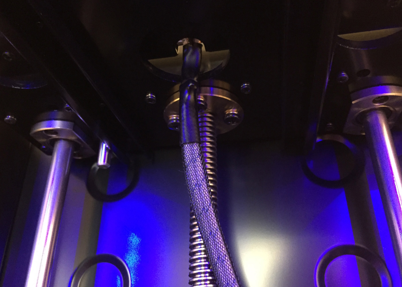
That looks like a lead screw. The screw should only move the X axis or undercarriage plate up and down- the lateral shift is probably caused by slop in the bearings that ride on the guide rails that should be parallel to the screw(s), and possibly slop in the bearings that the extruder carriage rides on, and possibly flex in any of the guide rails. There's no way to predict any or all of that slop so there's no way to correct for it in software. Assuming that everything is adjusted as well as it can be, the solution is to use better bearings/rails/and a stiffer frame.
You may be looking at the best print quality that the machine is capable of producing.
You may be looking at the best print quality that the machine is capable of producing.
|
Re: My z lead screw has a wobble to it and it can't be replaced so is there a software fix for Sli3r? June 12, 2015 07:27PM |
Registered: 11 years ago Posts: 1,049 |
Is this the printer
[www.3ders.org]
Looks like this is a leadscrew for the Z-Axis
Don't know why Digital dentist said it's X-Axis
"The screw should only move the X axis or undercarriage plate up and down- "
The soliddoodle printers had this problem with wobble and backlash in the Z-NUT on the Z-Axis leadscrew
--- a different leadscre NUT or loading the Z-Axis --- minimized the effects
If Japanese 3D printer company OPENCUBE can't fix it -- I would press to get my YEN back!!!!
|
Re: My z lead screw has a wobble to it and it can't be replaced so is there a software fix for Sli3r? June 13, 2015 03:53PM |
Registered: 9 years ago Posts: 93 |
Rods of any kind will 'wobble' to have a rod(s) that is very long with "no wobble" will cost you more than any budget 3dprinter will. If your z axis is held securely the wobble you can see while the rod spins is usually controlled well enough not to cause visible issues with the print. I agree with the digital dentist it could be x/y rigidity issues... slop/slack/deflection.
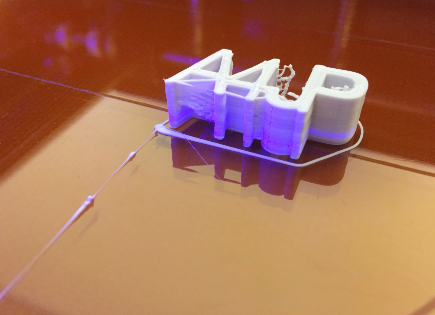
Though... there looks like there is a lot of over extruding going on which I believe could cause that printing issue depending on how much material is being packed into that area/which side the material flows. If the material extruded doesn't have space to go where it should, it flows wherever it can... and would look rough.
Though... there looks like there is a lot of over extruding going on which I believe could cause that printing issue depending on how much material is being packed into that area/which side the material flows. If the material extruded doesn't have space to go where it should, it flows wherever it can... and would look rough.
|
Re: My z lead screw has a wobble to it and it can't be replaced so is there a software fix for Sli3r? June 14, 2015 02:37AM |
Registered: 8 years ago Posts: 14 |
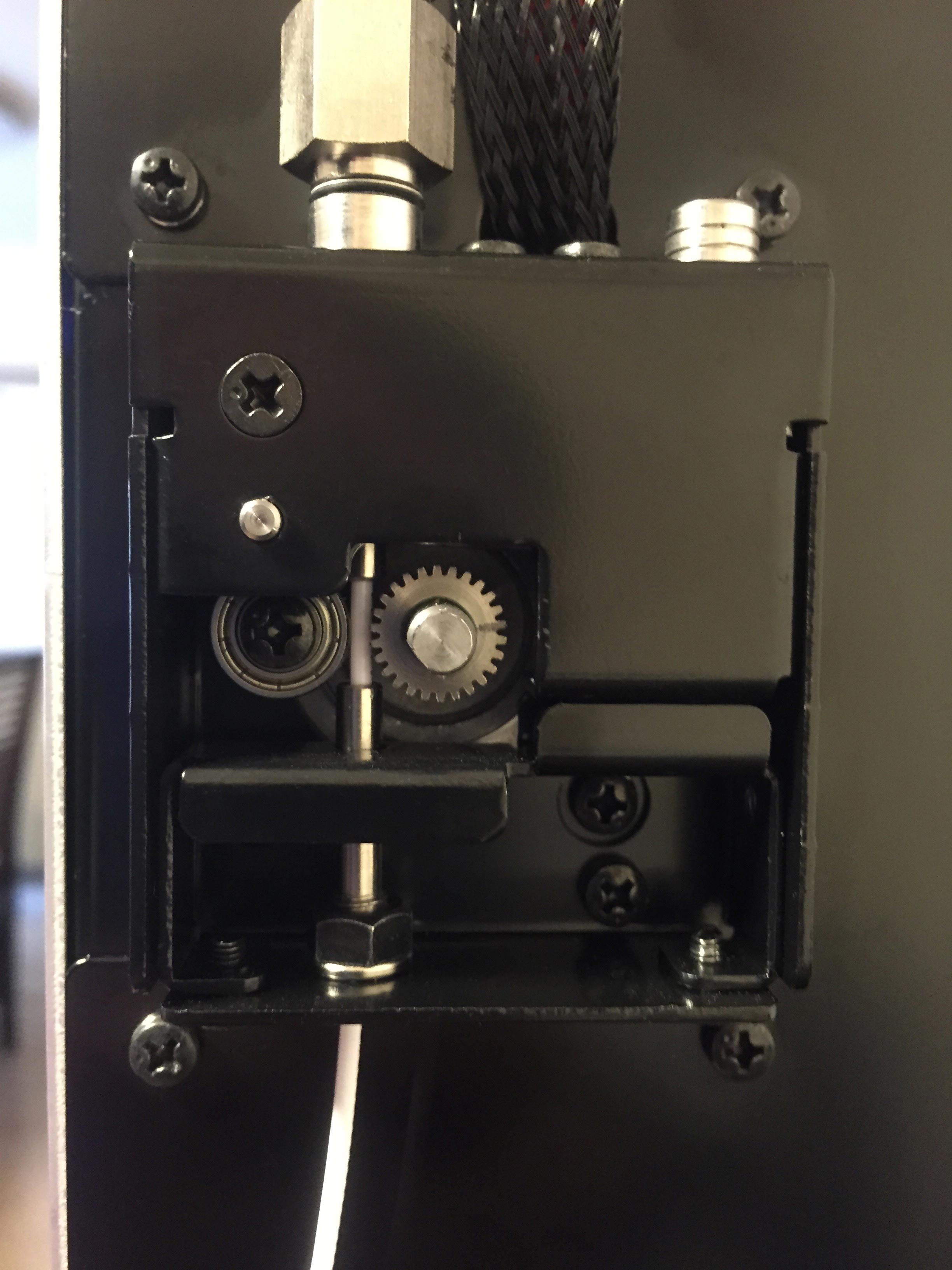
How can I calculate the correct E steps? I know the current value is 97.5 and the cog has 26 teeth. 98.8mm or 98.9mm comes out when I say give me 100mm in Pronterface. This is with no back pressure and only PLA going through the feeder.
#define DEFAULT_AXIS_STEPS_PER_UNIT {71.58,71.58,1066.67,97.5} // default steps per unit for ultimaker 123 //2014/02/28 105->100 105->90
#define DEFAULT_MAX_FEEDRATE {500, 500, 5, 25} // (mm/sec)
#define DEFAULT_MAX_ACCELERATION {9000,9000,100,10000} // X, Y, Z, E maximum start speed for accelerated moves. E default values are good for skeinforge 40+, for older versions raise them a lot.
#define DEFAULT_ACCELERATION 3000 // X, Y, Z and E max acceleration in mm/s^2 for printing moves
#define DEFAULT_RETRACT_ACCELERATION 3000 // X, Y, Z and E max acceleration in mm/s^2 for r retracts
// Offset of the extruders (uncomment if using more than one and relying on firmware to position when changing).
// The offset has to be X=0, Y=0 for the extruder 0 hotend (default extruder).
// For the other hotends it is their distance from the extruder 0 hotend.
// #define EXTRUDER_OFFSET_X {0.0, 20.00} // (in mm) for each extruder, offset of the hotend on the X axis
// #define EXTRUDER_OFFSET_Y {0.0, 5.00} // (in mm) for each extruder, offset of the hotend on the Y axis
// The speed change that does not require acceleration (i.e. the software might assume it can be done instantaneously)
#define DEFAULT_XYJERK 20.0 // (mm/sec)
#define DEFAULT_ZJERK 0.4 // (mm/sec)
#define DEFAULT_EJERK 5.0 // (mm/sec)
[a4jp.com] Scoovo 3D Printer
|
Re: My z lead screw has a wobble to it and it can't be replaced so is there a software fix for Sli3r? June 14, 2015 08:48AM |
Registered: 11 years ago Posts: 5,780 |
|
Re: My z lead screw has a wobble to it and it can't be replaced so is there a software fix for Sli3r? June 25, 2015 11:16PM |
Registered: 9 years ago Posts: 93 |
*I would also call over prime/under suck as 'over extrusion' I'm looking at how big you're blobbing(or REALLY thick stringing) in between shapes and the 'bubble' on top of the part. If you've measured ACTUAL to programmed and that's where you're at, I believe you. It looks to me that you've got a lot more material deposited than I believe should be.
|
Re: My z lead screw has a wobble to it and it can't be replaced so is there a software fix for Sli3r? January 21, 2016 10:14PM |
Registered: 8 years ago Posts: 14 |
I sent my printer back to the company to get the z rod replaced and it came back with a bit of a wobble so I opened up the printer.
The acme rod has 0.3mm wobble at the top of the rod only.
I can't revers it as the bottom has been machined into the right shape.
I undid the coupler and set it at the right height as it had slipped down.
The set screws on the coupler damaged the stepper motor's rod a little but I used pliers under the stepper to get the coupler off.
I want to find real tools for removing couplers in the future if there are any.
After grinding off the burs on the stepper motor rod with a diamond bit engraving piece everything went back together like it was new ^^
The top of the 3 disc coupler wobbles a tiny bit but I guess that isn't so important as it is means to move to allow for bends.
There is one other problem.
When I do up the set screw on the the coupler on the 14mm diameter threaded rod should I make sure the set screw hits the thread or it goes between the threads?
|
Re: My z lead screw has a wobble to it and it can't be replaced so is there a software fix for Sli3r? January 21, 2016 10:44PM |
Registered: 8 years ago Posts: 14 |
Sorry, only registered users may post in this forum.