Designing a reliable and accurate Z axis.
Posted by FalloutBe
|
Designing a reliable and accurate Z axis. May 22, 2015 03:06PM |
Registered: 9 years ago Posts: 63 |
Hello!
I am designing a new printer. The head moves around both the X and Y axis, and it works just fine.
The Z axis is my bed, which will move up and down.
I however have questions about in what way I should construct the Z axis, for it to be very acurate!
After typing this whole post, I realized that many people won't like to read this much text.
You don't really have to, the basic question is: Which Z axis design is, in your opinion, most accurate, and thin in height
I want the printer to be as compact as possible.
To keep the height of the printer low, I need the platform construction to be thin!
Using only 2 smooth rods, requires two bearings to be placed on each rod, to ensure the platform stays level. (just like in the Ultimaker)
Also, I never used or saw an ultimaker in real life, so I'm wondering, is the front of the bed secured? It looks like it being loose there, would allow it to move up or down a few tenths of a millimeter.
Using 4 smooth rods would be great because then the platform wouldn't take up much height. There is no need for placing multiple bearings above eachother to keep the platform level,
because the leadscrews or threaded rod will support the platform in each corner.
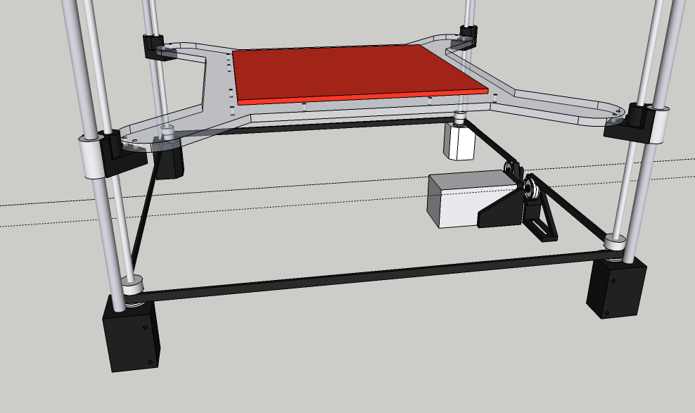
I have already created a Z axis with 4 smooth rods, 1 linear bearing on each rod, 1 threaded rod in each corner, and a pulley on each rod.
A belt goes all around the 4 pulleys, to make them rotate together.
(See attached image) -> as you can see here, the platform assembly is very thin; does not take up much Z height.
I really thought it would work great, but it turns out that, the pulleys rotating slightly (0.1mm) off center, causes the platform to be 0.002mm inaccurate.
When I print 0.05mm layers, that inaccuricy means that my layer height changes by 4% when the pulleys rotate. This is very visible in the result, the print is ugly.
(4% because when my belt moves 50mm, my platform moves for 1mm).
The reason for the pulleys to be off center, is that the threaded rods have an outer diameter of 4.95mm, and the hole for the pulleys is 5.00mm.
I've put a piece of plastic in the hole to get it rotating more around it's center point, but as soon as you start doing things like this, you know it'll never really be accurate.
You just have to ditch the whole idea, and start over with something new.
So, I should use lead screws, right?
But in this design, I had 4 smooth rods, which would then require 4 lead screws. This will be very expensive.
Another problem with the design was, that the threaded rods were difficult to secure in height. They needed to rotate, but their height needed to be fixed.
My lack of mechanical knowledge made this quite a failure, when they make a full rotation, they go up and down every time, for about 0.001mm.
My previous printer never had this problem! It was a prusa I3, and the threaded rods are mounted onto stepper motors,
which have exactly what I needed here, a shaft which can rotate, and which does not move up or down at all.
Again, if I want to implement that into my design, that would mean I need 4 Z motors, which is overkill.
Using only One motor would be great, but how do I make 4 rods rotate, with only 1 motor, without using this inaccuracte belt system?
I have considered using 3 or 4 of these
[ep.yimg.com]
but it is also quite expensive, and 3 or 4 motors for one movement action is not nice :/
Oh, and what about ball screw threaded rods?
This example seems fine:
[www.md-3d.com]
but what prevents the platform from tilting around the X axis?
I'm out of ideas now. Could anyone give me some hints? ^^ Thanks!
Edited 5 time(s). Last edit at 05/22/2015 03:20PM by FalloutBe.
I am designing a new printer. The head moves around both the X and Y axis, and it works just fine.
The Z axis is my bed, which will move up and down.
I however have questions about in what way I should construct the Z axis, for it to be very acurate!
After typing this whole post, I realized that many people won't like to read this much text.
You don't really have to, the basic question is: Which Z axis design is, in your opinion, most accurate, and thin in height
I want the printer to be as compact as possible.
To keep the height of the printer low, I need the platform construction to be thin!
Using only 2 smooth rods, requires two bearings to be placed on each rod, to ensure the platform stays level. (just like in the Ultimaker)
Also, I never used or saw an ultimaker in real life, so I'm wondering, is the front of the bed secured? It looks like it being loose there, would allow it to move up or down a few tenths of a millimeter.
Using 4 smooth rods would be great because then the platform wouldn't take up much height. There is no need for placing multiple bearings above eachother to keep the platform level,
because the leadscrews or threaded rod will support the platform in each corner.
I have already created a Z axis with 4 smooth rods, 1 linear bearing on each rod, 1 threaded rod in each corner, and a pulley on each rod.
A belt goes all around the 4 pulleys, to make them rotate together.
(See attached image) -> as you can see here, the platform assembly is very thin; does not take up much Z height.
I really thought it would work great, but it turns out that, the pulleys rotating slightly (0.1mm) off center, causes the platform to be 0.002mm inaccurate.
When I print 0.05mm layers, that inaccuricy means that my layer height changes by 4% when the pulleys rotate. This is very visible in the result, the print is ugly.
(4% because when my belt moves 50mm, my platform moves for 1mm).
The reason for the pulleys to be off center, is that the threaded rods have an outer diameter of 4.95mm, and the hole for the pulleys is 5.00mm.
I've put a piece of plastic in the hole to get it rotating more around it's center point, but as soon as you start doing things like this, you know it'll never really be accurate.
You just have to ditch the whole idea, and start over with something new.
So, I should use lead screws, right?
But in this design, I had 4 smooth rods, which would then require 4 lead screws. This will be very expensive.
Another problem with the design was, that the threaded rods were difficult to secure in height. They needed to rotate, but their height needed to be fixed.
My lack of mechanical knowledge made this quite a failure, when they make a full rotation, they go up and down every time, for about 0.001mm.
My previous printer never had this problem! It was a prusa I3, and the threaded rods are mounted onto stepper motors,
which have exactly what I needed here, a shaft which can rotate, and which does not move up or down at all.
Again, if I want to implement that into my design, that would mean I need 4 Z motors, which is overkill.
Using only One motor would be great, but how do I make 4 rods rotate, with only 1 motor, without using this inaccuracte belt system?
I have considered using 3 or 4 of these
[ep.yimg.com]
but it is also quite expensive, and 3 or 4 motors for one movement action is not nice :/
Oh, and what about ball screw threaded rods?
This example seems fine:
[www.md-3d.com]
but what prevents the platform from tilting around the X axis?
I'm out of ideas now. Could anyone give me some hints? ^^ Thanks!
Edited 5 time(s). Last edit at 05/22/2015 03:20PM by FalloutBe.
|
Re: Designing a reliable and accurate Z axis. May 22, 2015 03:39PM |
Registered: 10 years ago Posts: 869 |
The one that doesn't move.Quote
FalloutBe
Which Z axis design is, in your opinion, most accurate, and thin in height
You basically have discovered the drawback of that type of design. The successful printers that have implemented a bed that moves in the z-axis I think have done so with a single threaded rod/lead screw. As soon as you add more screws to the design, things get more and more complicated because you have to keep things in sync, and slight manufacturing differences or flaws of everyday threaded rod make using multiple of them complicated.
Edited 1 time(s). Last edit at 05/22/2015 04:14PM by cdru.
|
Re: Designing a reliable and accurate Z axis. May 22, 2015 03:47PM |
Registered: 9 years ago Posts: 63 |
"The one that doesn't move"
Haha, indeed (;
But Something has to move in the Z direction. I could lift up and down my XY assembly, which is basically the same (more difficult actually) as moving the bed up and down.
I'm quite stuck now with the idea of "really wanting the bed to be my Z axis" because I am really happy with how well the XY assembly performs.
"A single threaded rod/lead screw"
Oh yes, it would be great, but to get this mechanically strong, the rod should be in the center of the bed i.m.o. (only possible below it, as the print head is above).
This sadly makes the machine twice as tall because the rod needs to fit underneath the bed :/
(I was thinking, Z motor attached to the bed, and the sider attached to the bottom of the printer frame)
Oh, I should put a hole in my table on which the printer stands! It would hide the rod ^^
I really thought that, putting that single rod at one side of the bed, is bad. I can't imagine how the bed would be well secured like that,
but I can't say that it is not possible because I never felt how strong such a design is. You say it has been succesful.
Thanks for your input (;
Edited 1 time(s). Last edit at 05/22/2015 03:49PM by FalloutBe.
|
Re: Designing a reliable and accurate Z axis. May 22, 2015 04:46PM |
Registered: 10 years ago Posts: 869 |
Look at a Makerbot Replicator or Ultimaker printer. They have a single leadscrew on the back edge with a cantilevered build platform. It all comes down to how that bracket supports the bed. With appropriate bracketing, multiple linear bearings orientated vertically, and/or multiple lead screw nuts, you can make the force appear that it's coming from the middle when it's really coming from the side. Or you can reduce/eliminate the effect of torsional forces on the build platform. The smaller and lighter your platform is, the easier this task is. If you had a 1m by 1m square Alumnium plate bed, you're gonna have troubles. But if it's something a little more reasonable, then maybe it's possible. The thinner and thinner you want the overall z carriage height to be the less support it will have.Quote
FalloutBe
I really thought that, putting that single rod at one side of the bed, is bad. I can't imagine how the bed would be well secured like that,
but I can't say that it is not possible because I never felt how strong such a design is. You say it has been succesful.
|
Re: Designing a reliable and accurate Z axis. May 22, 2015 04:59PM |
Registered: 9 years ago Posts: 63 |
I know (: but it really needs to be thin.
Multiple linear bearings orientated vertically, which are only a few cm's apart, is going to be bad.
The platform will be about 30x30cm. I'd say that needs at least 10cm of spacing in between the bearings.
A cantilevered platform is something I really don't want in this design :/
Multiple linear bearings orientated vertically, which are only a few cm's apart, is going to be bad.
The platform will be about 30x30cm. I'd say that needs at least 10cm of spacing in between the bearings.
A cantilevered platform is something I really don't want in this design :/
|
Re: Designing a reliable and accurate Z axis. May 23, 2015 02:22AM |
Registered: 8 years ago Posts: 5,232 |
What I also don´t like with this kind of printer, is :
the heavy weight is at the top of the printer. Every moved mass has a perfect lever to bend and twist the frame. So it has to be extra stiff.
When I first saw the hobbyking fabrikator, I was amazed. But while I studied the design, I cooled down pretty fast and bought a prusa I3 instead.
-Olaf
the heavy weight is at the top of the printer. Every moved mass has a perfect lever to bend and twist the frame. So it has to be extra stiff.
When I first saw the hobbyking fabrikator, I was amazed. But while I studied the design, I cooled down pretty fast and bought a prusa I3 instead.
-Olaf
|
Re: Designing a reliable and accurate Z axis. May 29, 2015 06:31PM |
Registered: 9 years ago Posts: 396 |

|
Re: Designing a reliable and accurate Z axis. May 29, 2015 06:51PM |
Registered: 10 years ago Posts: 14,672 |
Quote
FalloutBe
"The one that doesn't move"
Haha, indeed (;
But Something has to move in the Z direction.
This is the big advantage of delta printers: the bed and the print don't move. The head moves in all 3 dimensions; but it is much lighter than the bed, assuming you use a Bowden extruder, and therefore easier to move.
Quote
FalloutBe
I'm quite stuck now with the idea of "really wanting the bed to be my Z axis" because I am really happy with how well the XY assembly performs.
There are at least the following ways of moving the bed in the Z direction:
1. Single leadscrew or threaded rod, and linear bearings. May be the best solution for small beds.
2. Multiple (typically 3 or 4) leadscrews driven from a single stepper motor via belts.
3. Multiple stepper motors driving leadscrews to support the bed, driven in series or in parallel. Problem is sync the motors when you turn the printer on.
4. Three stepper motors driving leadscrews, driven independently by the electronics. The firmware can use a Z probe to probe at least 3 points during Z homing, and adjust the 3 motors to get the bed level. I think this may be the best approach for really large beds. But it needs another 2 stepper motor drivers.
Large delta printer [miscsolutions.wordpress.com], E3D tool changer, Robotdigg SCARA printer, Crane Quad and Ormerod
Disclosure: I design Duet electronics and work on RepRapFirmware, [duet3d.com].
|
Re: Designing a reliable and accurate Z axis. May 30, 2015 01:22PM |
Registered: 9 years ago Posts: 63 |
Thank you for all your replies!
Something like this (example 2 of what dc42 has suggested) might be the best solution. 3 or 4 lead screws, driven by a belt and one single motor.
[wiki.germanreprap.com]
[mauk.cc]
Do you think it'll be necessary to add smooth rods to keep the platform in place?
Or would the leadscrews be stiff enough to keep the platform from moving sideways?
What do you think is the best way to secure the lead screws, to ensure they can't move up or down at all, but are free to rotate?
Also, ball screw or lead screw? Am I correct to say that a lead screw still has backlash?
Will this be qualitative? [www.ebay.com]
Edited 5 time(s). Last edit at 05/30/2015 01:39PM by FalloutBe.
|
Re: Designing a reliable and accurate Z axis. May 30, 2015 02:24PM |
Registered: 11 years ago Posts: 5,780 |
The second photo is interesting- it looks like they are using only ball screws to lift the bed without any linear bearings. I'm not sure that would work with lead screws - the nuts often fit pretty sloppily, but it might be OK will ball screws because the nuts fit with minimal play.
You don't need to worry about using antibacklash nuts- the weight of the print bed will keep the nuts loaded.
The auction you linked is just for ball nuts, not the screws. You'll need to get matching screws, preferably from the same manufacturer. I'd look for known good brand sets of screws and matching nuts. NSK, Thomson, etc.
|
Re: Designing a reliable and accurate Z axis. May 30, 2015 04:10PM |
Registered: 9 years ago Posts: 63 |
I had a prusa I3, where backlash wouldn't be a problem because gravity would keep the Z axis down.
However, when moving down,
because of little friction on the linear ball bearings sometimes the whole Z axis would "stick" in place, and then fall down after a while.
Ball screws seem Sooo damn expensive!
Oh, and I was looking on eBay for lead screws which have a round end (without thread on it), so that I can put a bearing around it, but I could not find that :/
I find only those that have the screw thread all across the rod.
Edited 1 time(s). Last edit at 05/30/2015 04:11PM by FalloutBe.
|
Re: Designing a reliable and accurate Z axis. May 30, 2015 05:12PM |
Registered: 11 years ago Posts: 5,780 |
I think the sticking was probably due to the use of bent threaded rods instead of lead screws.
What you have to do is chuck the screw in a lathe and turn down the ends for whatever size bearings you want to use. I don't know how difficult it is to cut the screw- it may require a grind stone instead of a cutter because it probably is/should be extremely hard steel.
What you have to do is chuck the screw in a lathe and turn down the ends for whatever size bearings you want to use. I don't know how difficult it is to cut the screw- it may require a grind stone instead of a cutter because it probably is/should be extremely hard steel.
|
Re: Designing a reliable and accurate Z axis. May 31, 2015 12:10AM |
Registered: 11 years ago Posts: 1,049 |
High resolution + thin = complex + expensive
What about something like this
[lh3.googleusercontent.com]
Perhaps CoreXZ
[forums.reprap.org]

What about something like this
[lh3.googleusercontent.com]
Perhaps CoreXZ
[forums.reprap.org]
|
Re: Designing a reliable and accurate Z axis. May 31, 2015 09:45AM |
Registered: 9 years ago Posts: 63 |
Alright, I think I'm going to go with 4 lead screws, driven by a belt (single motor).
Do you think I need smooth rods, or will 8mm lead screws provide enough strength to keep the platform from moving?
I also need some kind of bearing, which can rotate but keeps the lead screw from moving up or down.
I have no idea how this kind of bearing is called, can someone tell me please? ^^
Edited 1 time(s). Last edit at 05/31/2015 09:48AM by FalloutBe.
|
Re: Designing a reliable and accurate Z axis. June 01, 2015 09:49AM |
Registered: 10 years ago Posts: 869 |
A standard bearing like a 608 can handle radial as well as some axial forces. As long as you abuse the bearings and limit the axial forces, you shouldn't have a problem with them. There are better bearings if you want increased axial loads such a double-row angular contact or tapered roller ball bearings but are less common and more expensive and may not be readily available in very small sizes. For small bearings like the 608, the axial load rating is usually approximately 1/4 the static load rating. A typical 608 has a static load rating of around 1350N (300lbs) so a axial load rating around 337N (75lbs).Quote
FalloutBe
I also need some kind of bearing, which can rotate but keeps the lead screw from moving up or down.
I have no idea how this kind of bearing is called, can someone tell me please? ^^
|
Re: Designing a reliable and accurate Z axis. June 01, 2015 10:27AM |
Registered: 9 years ago Posts: 63 |
Ok. I will use regular bearings then, and put sone axial force on them to fix the backlash problem.
I did some research on how I need to mount the lead screw. To eliminate backlash, it turns out I have choice between:
- One bearing on each end of the screw, with nuts on the screw that push the two bearings apart. (like this example)
- Two bearings on one side with nuts that push the bearings together. (like this), and an additional bearing on the other end, just to keep the rod in place.
(in this second example, ignore the motor. In my case it'll be belt driven somehow)
I'd like to go with the second option, because it doesn't put any stress on the frame of the 3d printer.
Are there other ways of mounting them?
Do you think it is a good idea to put 8mm pulleys on the 8mm lead screw? Or is the actual outer diameter of the lead screw a bit less than 8mm?
Edited 2 time(s). Last edit at 06/01/2015 10:35AM by FalloutBe.
|
Re: Designing a reliable and accurate Z axis. June 01, 2015 03:05PM |
Registered: 10 years ago Posts: 869 |
Quote
FalloutBe
- One bearing on each end of the screw, with nuts on the screw that push the two bearings apart. (like this example)
This is referred to as a supported mount.
Quote
- Two bearings on one side with nuts that push the bearings together. (like this), and an additional bearing on the other end, just to keep the rod in place.
(in this second example, ignore the motor. In my case it'll be belt driven somehow)
This is referred to as a fixed mount.
Both types provide support, and are fixed attached. The differentiation is how the bearing handles moment forces. Moment forces are what a bearing handles when the shaft tries to flex while the bearing remains stationary. One side of the bearing in one direction while the other side pushes in the opposite. The fixed mount resists those forces better due to the spacing of the two bearings. This can allow for higher speeds and greater strength of the drive, but is more expensive and complicated to setup. If you are just using these to drive a z-axis up and down, honestly I don't think the mount type is going to be much of a determining factor. Speed is generally not an issue for the z-axis and moment forces will be minimal. Now if you were going to be using the machine for CNC routing or activities that would exert forces other than downwards, things would be different.
Quote
I'd like to go with the second option, because it doesn't put any stress on the frame of the 3d printer.
I'm not sure how you figure that. If the bearings are mounted to something, there's going to be stress.
Quote
Are there other ways of mounting them?
This might give you some more insight into mounting options.
Quote
Do you think it is a good idea to put 8mm pulleys on the 8mm lead screw? Or is the actual outer diameter of the lead screw a bit less than 8mm?
An 8mm ball screw will have a major diameter slightly less than 8mm. The usual way I believe is to step the shaft down, so for a 8mm lead screw, you may need to use a 6mm 626 bearing.
|
Re: Designing a reliable and accurate Z axis. June 01, 2015 03:08PM |
Registered: 8 years ago Posts: 5,232 |
|
Re: Designing a reliable and accurate Z axis. June 01, 2015 10:57PM |
Registered: 11 years ago Posts: 1,049 |
It is easy to OVER CONSTRAIN a leadscrew system
Motor, Coupler, bearings etc which binds up the mechanism.
Look at the difference between accuracy and precision
[www.protoparadigm.com]
How to Correctly Apply Lead Screws
[www.designworldonline.com]
Motor, Coupler, bearings etc which binds up the mechanism.
Look at the difference between accuracy and precision
[www.protoparadigm.com]
How to Correctly Apply Lead Screws
[www.designworldonline.com]
|
Re: Designing a reliable and accurate Z axis. June 02, 2015 10:05AM |
Registered: 9 years ago Posts: 63 |
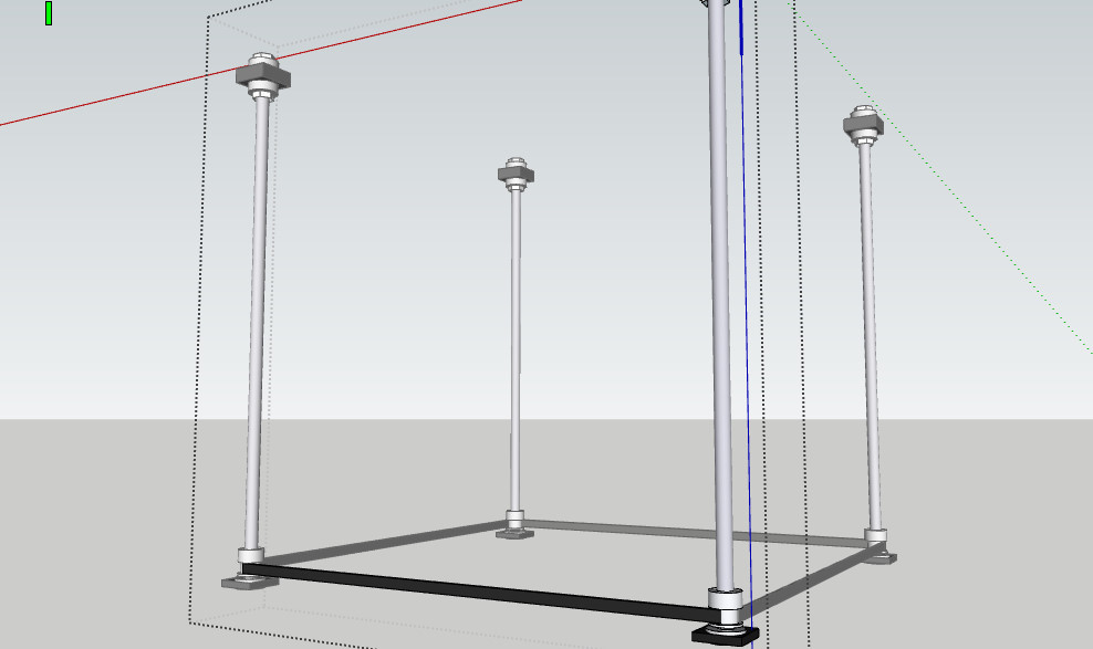
This is what currently seems like my best solution (see attachment)
4 lead screws, supported mount at the top to eliminate backlash, and pulleys at the bottom, with a bearing to keep it in place.
Motor and bed not shown, just to keep the drawing simple. Smooth rods will not be used, as there will not be much force on the bed in the X and Y direction.
What do you think of this?
If this is good, I'd like to go on to buying the components, but I still need to figure out how exactly I'm going to press the two top bearings together.
Just with M8 nuts? Would this be good or do I need rings with a clamping screw?
If I use M8 nuts, that means the bearing will need to have an inner diameter of 8mm, which might fit loosely around the rod, right? This is bad :/
I am worried about the M8 nuts that the side which will press on to the bearing will not be flat, perpendicular to the axis.
With regular nuts I saw that if you put them on a rod, and you rotate the rod, that the nuts are wobbling because they are poorly machined, Will this also happen with M8 nuts that are created for lead screws?
If this is also smaller than 8mm, I will indeed need to step down the shaft.
When using the second method, the stress will be applied to the whole height of the frame. That is what I meant (;
I do agree that a spring will be required, in case the nuts are not straight as I tried to explain above here.
Edited 1 time(s). Last edit at 06/02/2015 10:07AM by FalloutBe.
4 lead screws, supported mount at the top to eliminate backlash, and pulleys at the bottom, with a bearing to keep it in place.
Motor and bed not shown, just to keep the drawing simple. Smooth rods will not be used, as there will not be much force on the bed in the X and Y direction.
What do you think of this?
If this is good, I'd like to go on to buying the components, but I still need to figure out how exactly I'm going to press the two top bearings together.
Just with M8 nuts? Would this be good or do I need rings with a clamping screw?
If I use M8 nuts, that means the bearing will need to have an inner diameter of 8mm, which might fit loosely around the rod, right? This is bad :/
I am worried about the M8 nuts that the side which will press on to the bearing will not be flat, perpendicular to the axis.
With regular nuts I saw that if you put them on a rod, and you rotate the rod, that the nuts are wobbling because they are poorly machined, Will this also happen with M8 nuts that are created for lead screws?
How about a lead screw?Quote
cdru
An 8mm ball screw will have a major diameter slightly less than 8mm. The usual way I believe is to step the shaft down, so for a 8mm lead screw, you may need to use a 6mm 626 bearing.
If this is also smaller than 8mm, I will indeed need to step down the shaft.
Like in my attached image, this stress will only be applied to the black block at the top.Quote
cdru
I'm not sure how you figure that. If the bearings are mounted to something, there's going to be stress.
When using the second method, the stress will be applied to the whole height of the frame. That is what I meant (;
Do you mean in between the nuts that move the platform, or in between the nuts and the bearings at the top?Quote
o_lampe
I´ve seen simple versions with only a spring between the nuts.
I do agree that a spring will be required, in case the nuts are not straight as I tried to explain above here.
Edited 1 time(s). Last edit at 06/02/2015 10:07AM by FalloutBe.
|
Re: Designing a reliable and accurate Z axis. June 02, 2015 08:28PM |
Registered: 9 years ago Posts: 344 |
Hey, thank you all for discussing this. I am also designing my printer and after thinking, reading and discussing a lot, I am converging to a similar solution with the bed moving on Z, so hopefully my questions will be on topic.
Until 10 minutes ago I was thinking of using smooth rods and lead or ball screws. However the design with 3 ball screws and no smooth rods linked by FalloutBe is very appealing. But such a design implies high quality ballscrews with virtually no wobble, otherwise the result would be catastrophic: even a negligible wobble of amplitude 0.2mm would be very visible on a print.
So the question is: where to get ballscrews with such a precision at a reasonable price?
Here is some cheap Chinese stuff. It is not the best precision grade for sure, and maybe not even true.
Higher precision grades are also available but their price ranges from two to ten times as much even from China.
So after all maybe it is cheaper to keep smooth rods in the design instead of buying expensive ballscrews. What do you think?
One more question: nobody mentioned designs with 2 lead/ballscrews to lift the bed. Is there a particular reason?
I was thinking of using 4 smooth rods + 2 ballscrews for the Z axis. My bed will be standard (200x200 mm), so one ballscrew may be enough but I see symmetry as an additional guarantee of precision.
Edited 1 time(s). Last edit at 06/02/2015 08:30PM by cristian.
|
Re: Designing a reliable and accurate Z axis. June 03, 2015 12:03AM |
Registered: 11 years ago Posts: 1,049 |
I don't see 4 leadscrews in a Straysys Dimension 1200 3D printer?
Which is probably heavily engineered.
[www.google.com]
[forums.reprap.org]
Dimension 1200es spec
Layer thickness: 0.33 mm (0.013 in.) or .254 mm (.010 in.)
But I guess this is much more than you desire
and doesn't state z accuracy.
What size extrusion nozzle will you be using -- does it squirt at the accuracy you need?
See Accuracy column on chart at link below
then look at mechanisms?
[www.additive3d.com]
I think 4 screws are going to fight each other (over constrained system)
and the adjustment and sync is going to be near impossible.
?? Are you going to map the flatness of your build plate and compensate for this?
|
Re: Designing a reliable and accurate Z axis. June 03, 2015 09:12AM |
Registered: 11 years ago Posts: 5,780 |
There are two types of ball screws- rolled and ground. The cheapos are the rolled ones and specs won't be as good as the ground screws. The rolled screws (which is what the ones in the photo appear to be) might be adequate for z axis lift.
You might want to watch for ground ball screws and see what ebay turns up used.
You might want to watch for ground ball screws and see what ebay turns up used.
|
Re: Designing a reliable and accurate Z axis. June 03, 2015 05:50PM |
Registered: 11 years ago Posts: 1,049 |
BACKLASH --- occurs in leadscrew nuts, you are going to have
------ FOUR NUTS, one on each leadscrew attached to bed
------ will you be using loaded anti-backlash nuts or just nuts?
Bearings at top / bottom will constrain leadscrew vertical wobble
---- they won't do anything for any bow or squiggle in leadscrews
----- (bed movement in X / Y or leadscrew binding)
---- some have put leadscrews under tension to increase accuracy
---- mechanisms with guides use leadsrews with free end to prevent binding and focus on Z movement
Z Stepper motor ---- Where will it be mounted and how much contact with motor pulley?
----- 180 deg belt around pulley is desired
----- your drive pulleys look like only 90 degree contact
----- There is timing belt to timing belt pulley backlash -- you need precision pulley fitted to belt
----- It would be nice if helical timing belts / pulleys were available
IMHO
Your Four leadscrew solution has three un-necessary leadscrews to provide accurate Z motion
--- a rock solid table/bed which slides up and down very smoothly without any tilt or wobble
--- driven by a high quality lead/ball screw - very good anti-backlash nut attached to bed and one stepper motor with the best micro steps
Accuracy / precision
For your desired level of Z Accuracy / resolution
perhaps encoders on lead screw
or laser measurement of bed movement and full feedback to moving mechanism.
Example of a fine system
Hyrel system 30
[www.hyrel3d.com]
Precision Ball Screw in Z-axis
IKO Linear Bearing System in X, Y, and Z Axes, rated to
20,000km before first manufacturer suggested lubrication
Posional Resoluon
Z Axis 200 mm +/- 20 microns < 1 micron
|
Re: Designing a reliable and accurate Z axis. June 03, 2015 07:52PM |
Registered: 9 years ago Posts: 344 |
|
Re: Designing a reliable and accurate Z axis. June 03, 2015 08:07PM |
Registered: 9 years ago Posts: 344 |
Quote
the_digital_dentist
There are two types of ball screws- rolled and ground. The cheapos are the rolled ones and specs won't be as good as the ground screws. The rolled screws (which is what the ones in the photo appear to be) might be adequate for z axis lift.
You might want to watch for ground ball screws and see what ebay turns up used.
There are several auctions for used ground ball screws, and they are quite expensive too. In my case I will probably go the (not so) cheap way first with one standard quality rolled screw, then upgrade to higher number and/or quality if I see that the precision is not enough for what I have to do. I expect the Z axis being a minor concern anyway, given all the other sources of problems...
|
Re: Designing a reliable and accurate Z axis. June 03, 2015 10:15PM |
Registered: 11 years ago Posts: 1,049 |
I don't have any specifics.
I think the laser measurement sensors with this precision are very expensive
and I know of no 3D control software that uses any type of measurement feedback.
There are many 3D scanners that precisely map 3D object and produce measurement files.
A digital caliper with signal output may be of use.
I used a digital readout scale to measure movement of my Wally bed -- very accurate -- 0.XX mm
Quote
cristian
Quote
cozmicray
or laser measurement of bed movement and full feedback to moving mechanism.
May you post some link for such measurement tools?
|
Re: Designing a reliable and accurate Z axis. June 04, 2015 11:51AM |
Registered: 9 years ago Posts: 63 |
Thanks again cozmicray, for all your help (;
I'm going for the cantilevered platform, 4 bearings, 2 smooth rods and a single lead screw.
What do you think will be best?
[www.ebay.com] (delrin nut)
or
[www.ebay.com] (motor attached, regular nut)
or
[www.ebay.com] (motor attached, regular nut, coupler)
?
The delrin nut states to have much better resolution, and it is cheaper.
The regular lead screws all seem to have an 8mm pitch, which I think is too large.
Anti backlash nuts or regular nuts?
The sets on ebay don't have anti backlash nuts :/ Do you think it is necessary?
Gravity should keep it down, but my platform is moving downwards along the print, so it might stick.
EDIT: I want at least 20micron layers!
Edited 1 time(s). Last edit at 06/04/2015 11:52AM by FalloutBe.
|
Re: Designing a reliable and accurate Z axis. June 04, 2015 12:19PM |
Registered: 9 years ago Posts: 344 |
Quote
FalloutBe
Thanks again cozmicray, for all your help (;
I'm going for the cantilevered platform, 4 bearings, 2 smooth rods and a single lead screw.
What do you think will be best?
[www.ebay.com] (delrin nut)
or
[www.ebay.com] (motor attached, regular nut)
or
[www.ebay.com] (motor attached, regular nut, coupler)
?
The delrin nut states to have much better resolution, and it is cheaper.
The regular lead screws all seem to have an 8mm pitch, which I think is too large.
Anti backlash nuts or regular nuts?
The sets on ebay don't have anti backlash nuts :/ Do you think it is necessary?
Gravity should keep it down, but my platform is moving downwards along the print, so it might stick.
EDIT: I want at least 20micron layers!
As usual, vendors "forget" to give precision grades...
|
Re: Designing a reliable and accurate Z axis. June 04, 2015 12:29PM |
Registered: 11 years ago Posts: 1,049 |
20µ= 0.020mm i.e. one fifth of the thickness of paper?
With extrusion nozzles at 0.2 ---- 0.6 mm
How are you going to squirt out a 0.02mm layer
even if layer is smooshed down by 50% ---- 0.020mm layer tough?
Some say 40 micron is perfect
I would research how small a layer can be extruded.
and the six days required to print an object???
May have to go to photoresin printer?
So your table movement may be moot!

Sorry, only registered users may post in this forum.