Threadless Leadscrew ???
Posted by cozmicray
|
Threadless Leadscrew ??? March 21, 2014 06:59PM |
Registered: 11 years ago Posts: 1,049 |
I am looking into the use of threadless leadscrew on 3D printer
I have set up test rig
36" 12mm stainless steel rod
between two flange bearings
12" DRO for measurement
=============================
Rider is customised thingiverse #125529
Parameters
Gap T 1
Bearing dia 22mm
Bearing ht 7mm
Bearing ID 7.9mm
Rod OD 13mm
Pitch 30
Bearing offset 30
Mount ht 13mm
base nut 8
base bolt 5
compression nut 10
compression bolt 8
race offset 0.25
============================
Drive is an Arduino Uno with a GRBL shield
GRBL firmware
UGS software
5mm - 12mm coupling both hard/flexible tried
Takes me about 3 hours to print up different riders on my Ordbot Hadron
I run the test rig back and forth (standing vertical) for 100 units (~100mm)
noting the reading on the DRO.
I've got all kinds of data that makes little sense or is showing this is a terrible idea
Anyone else out there got any data on threadless Leadscrew?
|
Re: Threadless Leadscrew ??? March 21, 2014 08:13PM |
Registered: 10 years ago Posts: 1,381 |
I'd like to see this work, it has a lot of benefits.
Based on your comments it sounds like the data has large volatility,
and is far from the expected (mean) value, and it's obvious to you that it's not working.
But I'm curious, post your data, and collection method (manual/automatic).
Depending on your data I might be able to evaluate it, and it depends on if my bespoke statistical model is suited for your data.
Typo?
I've evaluated an industrial threadless bearing before, and it does not work on a piece of cold rolled SS rod.
It needs a harden ground rod, I didn't use it in my mfg equipment design.
What is the significance of this comment, i.e. how does it effect the results.
Was there any slop/wiggle movement between the ID of the bearing, and the shaft that passed through the bearing, (e.g. it should be a press fit).
I'd like to see pics of your setup, and of the bearing retainer.
What material did you print the bearing retainer with.
How much infill did you use.
Based on the image in the link, I'm inclined to say that it needs to be more ridged across the board.
[www.thingiverse.com]
Edited 2 time(s). Last edit at 03/23/2014 07:32AM by A2.
Based on your comments it sounds like the data has large volatility,
and is far from the expected (mean) value, and it's obvious to you that it's not working.
But I'm curious, post your data, and collection method (manual/automatic).
Depending on your data I might be able to evaluate it, and it depends on if my bespoke statistical model is suited for your data.
Quote
cozmicray
36" 12mm stainless steel rod
Rod OD 13mm
Typo?
I've evaluated an industrial threadless bearing before, and it does not work on a piece of cold rolled SS rod.
It needs a harden ground rod, I didn't use it in my mfg equipment design.
Quote
cozmicray
between two flange bearings
What is the significance of this comment, i.e. how does it effect the results.
Was there any slop/wiggle movement between the ID of the bearing, and the shaft that passed through the bearing, (e.g. it should be a press fit).
I'd like to see pics of your setup, and of the bearing retainer.
What material did you print the bearing retainer with.
How much infill did you use.
Based on the image in the link, I'm inclined to say that it needs to be more ridged across the board.

[www.thingiverse.com]
Edited 2 time(s). Last edit at 03/23/2014 07:32AM by A2.
|
Re: Threadless Leadscrew ??? March 22, 2014 05:19PM |
Registered: 11 years ago Posts: 1,049 |
I gather data manually
zero DRO
send cmd via UGS to arduino/grbl (UGS Universal G-code Sender)
read/record DRO reading
Flange bearing is 12mm ID bearing mounted in flange with two screw holes on flange
the bearing has two set screws on inner race to anchor to rod
All riders (thing with 6 bearings that rides up/down rod)
broke and were repaired with drilling and sheet metal screws post break
I'll dig out print data.
Here is some data gathered on 3-22-2014 (spreadsheet format):
Silver rider printed on Aluminatus A1 at Vermont Rapid Protyping

|
Re: Threadless Leadscrew ??? March 22, 2014 06:03PM |
Registered: 10 years ago Posts: 1,381 |
I was not expecting 1 mm to 4 mm range.
Max: 100.28 mm
Min: 99.19 mm
Range: 1.09 mm
Max: 103.95 mm
Min: 99.61 mm
Range: 4.34 mm
If you operate it by hand does it feel like it's slipping.
My guess is that the inertia of the rotating shaft is causing the bearings to slip, or the shaft is translating.
Max: 100.28 mm
Min: 99.19 mm
Range: 1.09 mm
Max: 103.95 mm
Min: 99.61 mm
Range: 4.34 mm
If you operate it by hand does it feel like it's slipping.
My guess is that the inertia of the rotating shaft is causing the bearings to slip, or the shaft is translating.
|
Re: Threadless Leadscrew ??? March 22, 2014 06:10PM |
Registered: 11 years ago Posts: 1,049 |
CozmicRay's Threadless Leadscrew quest
Photos of my test rig:
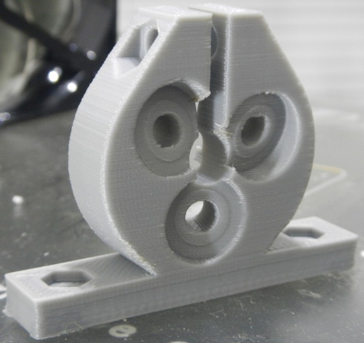
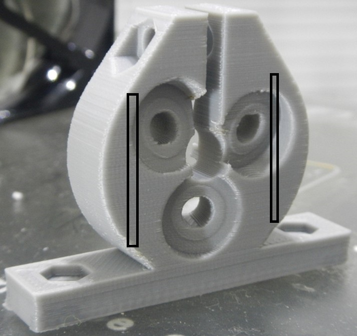
Cracked rider --- seems like all of them break in the area on both sides
Stepper drive Nema 17 with solid aluminum coupler, I machined 5mm - 12mm ID
DRO read out
Flange bearing on top/bottom end of rod mounting
note set screws radially anchor inner race to rod
No tension on rod for these tests
Rider with connection to DRO rail
---- note screws that clamp clacked area back to base
are we having phun yet?

Photos of my test rig:
Cracked rider --- seems like all of them break in the area on both sides

Stepper drive Nema 17 with solid aluminum coupler, I machined 5mm - 12mm ID
DRO read out

Flange bearing on top/bottom end of rod mounting
note set screws radially anchor inner race to rod
No tension on rod for these tests

Rider with connection to DRO rail
---- note screws that clamp clacked area back to base


are we having phun yet?
|
Re: Threadless Leadscrew ??? March 22, 2014 06:23PM |
Registered: 11 years ago Posts: 1,049 |
I am tesing with rig near vertical ~80 deg.
I figured worst case for Threadless Leadscrew
and how it would be used in Lisa Simpson.
I get the motor stalling out if a crank down on tension screw on rider.
It is very sesitive to tension or rider
Might look for double stack nema 17 or nema 23
this nema 17 just on 12v and not pulling much current
I can try to adjust that on grbl board
doesn't seem like the rider is slipping
--- I'll put some marks on rider bearings to see smooth rotation
--- maybe need a encoder on shaft to see if stepper is skipping
I though 10 runs would show slips or gotchas
It was neat to see it run fast at F=1500
skips and stalls at 2000 /2500
suggestions appreciated?
|
Re: Threadless Leadscrew ??? March 22, 2014 07:26PM |
Registered: 10 years ago Posts: 1,381 |
OK, so you have a few mechanical, and design issues to work out.
Barring improving the fusion between layers, change the print orientation, and consider trying a solvent vapor bath to improve the strength of the rider.
You could also drill a hole, and press a metal rod perpendicular to the crack to give the rider strength.
Use epoxy to prevent the rod from moving.
If the DRO scale is not perfectly parallel to the shaft it will add to the error.
I've set these up before on a lathe, Bridgeport, boring mill, and you really need to mount the DRO as perfect as possible, or the reading will be off.
Mount an indicator onto the scale, and the stylus onto the shaft to verify in the X and Y planes.
Doesn't sound right that the motor would completely stall, but it's not totally out of the realm of possibilities.
With the stepper removed, is it easy to rotate the shaft with the retainer torqued down.
If the motor is not aligned with the shaft, some torque could be lost, maybe try a flexible coupler .
I recall the one that I evaluated had stuckation issues on a non precision shaft.
Edited 1 time(s). Last edit at 03/22/2014 07:27PM by A2.
Barring improving the fusion between layers, change the print orientation, and consider trying a solvent vapor bath to improve the strength of the rider.
You could also drill a hole, and press a metal rod perpendicular to the crack to give the rider strength.
Use epoxy to prevent the rod from moving.

If the DRO scale is not perfectly parallel to the shaft it will add to the error.
I've set these up before on a lathe, Bridgeport, boring mill, and you really need to mount the DRO as perfect as possible, or the reading will be off.
Mount an indicator onto the scale, and the stylus onto the shaft to verify in the X and Y planes.
Quote
cozmicray
I get the motor stalling out if a crank down on tension screw on rider.
It is very sesitive to tension or rider
Doesn't sound right that the motor would completely stall, but it's not totally out of the realm of possibilities.
With the stepper removed, is it easy to rotate the shaft with the retainer torqued down.
If the motor is not aligned with the shaft, some torque could be lost, maybe try a flexible coupler .
I recall the one that I evaluated had stuckation issues on a non precision shaft.
Edited 1 time(s). Last edit at 03/22/2014 07:27PM by A2.
|
Re: Threadless Leadscrew ??? March 27, 2014 05:27PM |
Registered: 11 years ago Posts: 1,049 |
Some more data
Added weight to rider 12.9 oz and 27.9 oz test runs
weight sits right above compression screw.
doesn't seem to matter much
on up travels system balks ---- ?? motor ??? coupler
Added weight to rider 12.9 oz and 27.9 oz test runs
weight sits right above compression screw.

doesn't seem to matter much
on up travels system balks ---- ?? motor ??? coupler
|
Re: Threadless Leadscrew ??? March 27, 2014 05:41PM |
Registered: 10 years ago Posts: 1,381 |
That's still a lot of error.
The whole device needs to be rigid.
Did you redesign, and beef up the rider (pics).
Is there any wiggle between the inner and outer race.
Is the shaft passing through the bearing a press fit, and anchored solid to the rider.
Do the speeds represent real world application.
Is the shaft the correct size.
There are videos of the threadless screw working on the Z axis, have your reviewed them.
[www.youtube.com]
|
Re: Threadless Leadscrew ??? March 27, 2014 09:42PM |
Registered: 11 years ago Posts: 1,049 |
|
Re: Threadless Leadscrew ??? March 27, 2014 11:39PM |
Registered: 10 years ago Posts: 1,381 |
This printer is using threadless ball screws on each axis, and the retainers look like they are 2x thicker, but he is having problems with inconsistent prints.
Spiral Vase Mode Threadless Ballscrew Printer Printing
its consistantly inconsistant but works for shapes like the vases when some creative slant does not really detract, putting it aside for a while, need to get some other projects done then will add magnetic encoder. that vase completed in 1 piece though and was 120mm tall at the end
[www.youtube.com]
using a 6 bearing assembly with angled bearings to achieve a 15mm pitch on a smooth 10mm rod, no thread required.when all bearings are fastening correctly on a well printed bearing holder the pitch is repeatable and accurate. It does require a bearing mount at each end of the center smooth rod to be even better,
[www.youtube.com]
Spiral Vase Mode Threadless Ballscrew Printer Printing
its consistantly inconsistant
but works for shapes like the vases when some creative slant does not really detract, putting it aside for a while, need to get some other projects done then will add magnetic encoder. that vase completed in 1 piece though and was 120mm tall at the end[www.youtube.com]
using a 6 bearing assembly with angled bearings to achieve a 15mm pitch on a smooth 10mm rod, no thread required.when all bearings are fastening correctly on a well printed bearing holder the pitch is repeatable and accurate. It does require a bearing mount at each end of the center smooth rod to be even better,
[www.youtube.com]
|
Re: Threadless Leadscrew ??? March 28, 2014 12:31PM |
Registered: 11 years ago Posts: 1,049 |
Thanks for the input?
These use guides along with the leadscrew.
Lisa Simpson forbids the use of guides.
What are realistic movement speeds for leadscrew on 3D printer?
My tests at 500, 1000, 1200, 1500, 2000, 2500 mm/min.
Got any other ideas on threadless leadscrew rider design
out there that can be designed around 12mm rod
that may get better accuracy?
|
Re: Threadless Leadscrew ??? March 28, 2014 12:43PM |
Registered: 11 years ago Posts: 1,049 |
|
Re: Threadless Leadscrew ??? March 28, 2014 01:06PM |
Registered: 10 years ago Posts: 1,381 |
Micro tracks lapped into the harden shaft would prevent the bearing edge from loosing it's registration.
Idea:
Use Clover lapping compound, and lap micro tracks into the shaft to guide the bearings.
Wrap the shaft with foam to hold the lapping compound.
The arms tethered at the hub act as the guide.
The retainer doesn't rotate, the shaft does.
Idea:
Use Clover lapping compound, and lap micro tracks into the shaft to guide the bearings.
Wrap the shaft with foam to hold the lapping compound.
Quote
cozmicray
These use guides along with the leadscrew.
Lisa Simpson forbids the use of guides.
The arms tethered at the hub act as the guide.
The retainer doesn't rotate, the shaft does.
|
Re: Threadless Leadscrew another rider March 30, 2014 03:08PM |
Registered: 11 years ago Posts: 1,049 |
Different rider (Blue rider 1)based on thingiverse 124706 mod in scad
Had to cut it to provide adjustable compression
Bearings don't run flat on rod but edge digs in
even creating score on SS rod
Here is some data (speed and accelation changes):
Had to cut it to provide adjustable compression
Bearings don't run flat on rod but edge digs in
even creating score on SS rod

Here is some data (speed and accelation changes):

|
Re: Threadless Leadscrew yet another rider March 30, 2014 03:16PM |
Registered: 11 years ago Posts: 1,049 |
Another version of rider (Blue rider 2) thingiverse 124706
again cut to provide relief, Bearings really cut into SS rod
only three bearings on this one
Here's the data (94.653 steps/mm, various speeds):
again cut to provide relief, Bearings really cut into SS rod
only three bearings on this one


Here's the data (94.653 steps/mm, various speeds):

|
Re: Threadless Leadscrew some video March 30, 2014 05:02PM |
Registered: 11 years ago Posts: 1,049 |
You can look at some video of my testing
various speeds on test set up
with Blue 1 Rider
[www.youtube.com]
various speeds on test set up
with Blue 1 Rider
[www.youtube.com]
|
Re: Threadless Leadscrew some video March 30, 2014 08:40PM |
Registered: 10 years ago Posts: 1,381 |
|
Re: Threadless Leadscrew ??? March 30, 2014 11:02PM |
Registered: 11 years ago Posts: 1,049 |
Rod is:
17-4 PH Stainless Steel Round Rod 12 mm
17-4 Precipitation Hardening (PH) Stainless Steel combines high strength with corrosion resistance. The alloy is also known as 630 Stainless. 17-4PH has approximately the same heat and corrosion resistance as the 304 alloy.
Material: Stainless Steel
Alloy: 17-4 Stainless
Shape: Round Rod
Diameter: 12mm
Condition: H900
Finish: Turned, Ground and Polished
Hardness: RC 45-47
Notes: Tolerances: Diameter: (+0/-.0005) | Length (+/- 1/8")
|
Re: Threadless Leadscrew ??? March 31, 2014 10:21PM |
Registered: 10 years ago Posts: 1,381 |
Not a favorable report on this thread.
Threadless Ball Screws
[forums.reprap.org]
Looking at McMaster Carr, as supplied 17-4 is RC44 which is on the soft side compared to harden rods for bearings RC60.
Corrosion-Resistant High-Strength 17-4 PH Stainless Steel
[www.mcmaster.com]
Hardened Shafts with Tapped Mounting Holes
[www.mcmaster.com]
Soft rods will wear a grove with pressure waves (just like what you find on a gravel road or sandy trail), and will cause the threadless lead screw to bind.
Another concern is the plastic retainer creeping over time, and reduce the pressure/grip.
The threadless bearing that I reviewed used an aluminum block, and I couldn't get it to work on a ground SS rod, because it wore groves into the shaft.
It would stutter, and bind up rather quickly.
I think the last thing to try is to lap a track/race/grove for the bearing to follow into harden steel.
The track wouldn't have to be very deep to guide the bearing, and if you program the stepper to automatically go back and forth it might not take much effort to test it.
|
Re: Threadless Leadscrew ??? April 01, 2014 05:44PM |
Registered: 11 years ago Posts: 1,049 |
So I need some type of unobtainium special metal rod that costs $14 million
If I lap threads in rod ---- then is NOT a threadless leadscrew
If I lap threads in rod ---- then is NOT a threadless leadscrew
Quote
A2
Not a favorable report on this thread.
Threadless Ball Screws
[forums.reprap.org]
Sorry I don't read German
Looking at McMaster Carr, as supplied 17-4 is RC44 which is on the soft side compared to harden rods for bearings RC60.
Corrosion-Resistant High-Strength 17-4 PH Stainless Steel
[www.mcmaster.com]
Hardened Shafts with Tapped Mounting Holes
[www.mcmaster.com]
Soft rods will wear a grove with pressure waves (just like what you find on a gravel road or sandy trail), and will cause the threadless lead screw to bind.
Another concern is the plastic retainer creeping over time, and reduce the pressure/grip.
The threadless bearing that I reviewed used an aluminum block, and I couldn't get it to work on a ground SS rod, because it wore groves into the shaft.
It would stutter, and bind up rather quickly.
I think the last thing to try is to lap a track/race/grove for the bearing to follow into harden steel.
The track wouldn't have to be very deep to guide the bearing, and if you program the stepper to automatically go back and forth it might not take much effort to test it.
|
Re: Threadless Leadscrew ??? April 01, 2014 10:01PM |
Registered: 10 years ago Posts: 1,381 |
It would be nice to know where the slipping is occurring.
I can only think of one test, and that is to ramp up the speed slowly, and stop slowly.
Would that help to maintain registry, or is it slipping some where in the middle of the rod.
I think the combination of a plastic retainer and soft steel is not going to work.
The heat treat process for 17-4 PH Stainless Steel is not complicated, elevate the temperature for a few hours, then air cool.
You could try case hardening the metal that you have.
An old school technique is to wrap the metal in leather, then seal it in a SS foil crucible, and case harden it.
But you will have to OD grind it, so that's probably not an option for you.
I like the idea of shallow groves in harden steel, but if you can't source the rods, and don't like the idea of groves, then I guess unfortunately this is the end.
|
Re: Threadless Leadscrew Inverted April 03, 2014 04:23PM |
Registered: 11 years ago Posts: 1,049 |

|
Re: Threadless Leadscrew Inverted April 03, 2014 09:38PM |
Registered: 10 years ago Posts: 1,381 |
In your notes you have mentioned a few times "skip bind".
I assume at those times it was obvious to the unaided eye that there was a problem.
Maybe there is micro skip binding going on that you can't see, and the error is accumulated.
I think this would indicate that the soft rod is at fault.
It is interesting that your error has been reduced by orientating the rod vertical.
You've added a load to the retainer by doing this.
Maybe it needs a mass attached to it.
|
Re: Threadless Leadscrew Inverted April 04, 2014 12:52PM |
Registered: 11 years ago Posts: 1,049 |
|
Re: Threadless Leadscrew ??? April 06, 2014 03:00PM |
Registered: 10 years ago Posts: 9 |
I've never gotten a good answer to this, but why couldn't we use a similar printed part with 3 or 4 bearings, and have them run on a standard threaded rod? Couldn't the edge of the bearing roll between two threads? (to totally eliminate slipping concerns)
This seems obvious, so I'm guessing there is some reason. Is it that the pitch of most threaded rods would make for an unacceptable speed?
Thanks for the clarification and the work done on this. I've printed out a few and noticed my smooth rod did develop grooves, but never used them for anything.
Edited 1 time(s). Last edit at 04/06/2014 03:01PM by orangezero.
|
Re: Threadless Leadscrew ??? April 06, 2014 03:45PM |
Registered: 10 years ago Posts: 1,381 |
@orangezero:
I like the idea,it should be tested.
You wouldn't need to compress the bearing edge into the metal, so it might work.
But if a pressure wave builds up in front of the bearing because the threads are not harden, the issues are the same (stuckation).
You could use a 10 pitch thread.
I like the idea,it should be tested.
You wouldn't need to compress the bearing edge into the metal, so it might work.
But if a pressure wave builds up in front of the bearing because the threads are not harden, the issues are the same (stuckation).
You could use a 10 pitch thread.
|
Re: Threadless Leadscrew ??? April 07, 2014 12:32PM |
Registered: 11 years ago Posts: 1,049 |
Threadless leadscrew
Eliminate high price of precision lead/ballscrew
I can't see what bearings riding on a threaded rod
has any advantage over a proper nut?
I don't see industry jumping to do this?
Want bearings on a threaded rod -- shell out big bucks for a ballscrew.
There is much testing to do here.
I think the individual bearing pressure on the rod has a lot to do with it.
When I increase the compression on the riders I have used
it stalls out the drive motor
Perhaps 5hp high torque motor driving rod
with heavily compressed rider would provide accuracy.
NO ONE is developing this and doing real testing!
"I've never gotten a good answer to this, but why couldn't we use a similar printed part with 3 or 4 bearings, and have them run on a standard threaded rod? Couldn't the edge of the bearing roll between two threads? (to totally eliminate slipping concerns)"
|
Re: Threadless Leadscrew ??? April 07, 2014 03:31PM |
Registered: 10 years ago Posts: 1,381 |
Quote
cozmicray
I can't see what bearings riding on a threaded rod has any advantage over a proper nut?
By running bearings in the groves of a threaded rod you have the basics of a ball screw, which affords low rolling friction, low assembly force, and zero backlash.
Threadless ballscrew, "rolling ring drive"
Another form of linear actuator based on a rotating rod is the threadless ballscrew, a.k.a. "rolling ring drive".
In this design, three (or more) rolling-ring bearings are arranged symmetrically in a housing surrounding a smooth (thread-less) actuator rod or shaft.
The bearings are set at an angle to the rod, and this angle determines the direction and rate of linear motion per revolution of the rod.
An advantage of this design over the conventional ballscrew or leadscrew is the practical elimination of backlash and loading caused by preload nuts.
[en.wikipedia.org]
|
Re: Threadless Leadscrew ??? April 07, 2014 04:48PM |
Registered: 11 years ago Posts: 1,049 |
Put new coupler on motor drive
24v power to grbl shield driving motor
more testing with Blue 2 rider,
doesn't skip or bind as much
with DRO
and
with digital dial gauge at bottom of travel
lots of error with dial gauge measurement -1.881 greater travel error (-0.0188 per mm)
24v power to grbl shield driving motor
more testing with Blue 2 rider,
doesn't skip or bind as much
with DRO
and
with digital dial gauge at bottom of travel
lots of error with dial gauge measurement -1.881 greater travel error (-0.0188 per mm)


Sorry, only registered users may post in this forum.