Drylin Linear Guides
Posted by uGen
|
Re: Drylin Linear Guides February 05, 2013 06:21PM |
Admin Registered: 16 years ago Posts: 13,886 |
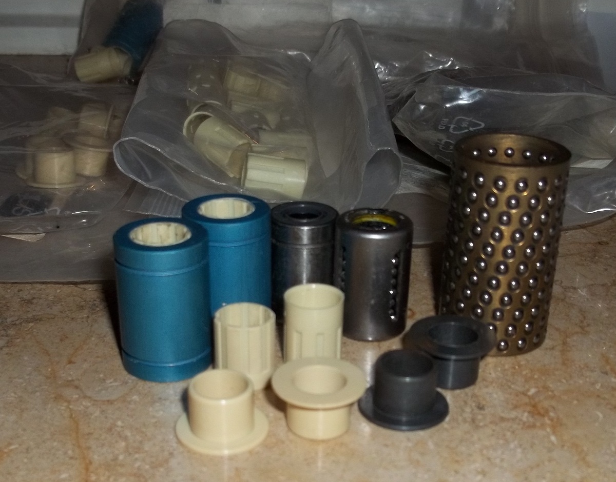
Igus has several 'ball-bushing replacements' and gliders with press-fit or wear-in or 'playing' fittings.
In the image are some of the older replacements (the left one with visible wear) and some axial and radial gliders - could be other types today.
I could order them then with any wished under- or over-measure ...
Viktor
--------
Aufruf zum Projekt "Müll-freie Meere" - [reprap.org] -- Deutsche Facebook-Gruppe - [www.facebook.com]
Call for the project "garbage-free seas" - [reprap.org]
|
Re: Drylin Linear Guides February 05, 2013 06:58PM |
Registered: 11 years ago Posts: 490 |
-VDX: Thank you for your explanation, didn't expect play in that direction...
You really have got the most exquisite stuff lying around! Nanometer precision sure sounds interesting for polar bots (a robot arm printer with better than 0.05mm accuracy would be awesome).
Now piezo actuators are another topic that I would love to see development in. Last I searched, little smd piezo crystals cost about 50€ per roll of 50, though; still cheap compared to the prices for assembled actuators by the same manufacturer (PCBMotor).
-Pacca: Funny how the same person who later built the Aluminatus (really a beautiful machine IMHO) said that leadscrews were overkill for RepRaps because of limitations in the electronics. Nothing against them, though. I think they use ARM based electronics on their machine, so this argument does not hold anymore. I, too, considered leadscrews like these for a while, but they are much more annoying to set up and more expensive than a GT timing belt system with 2 times reduction via pulleys that has slightly more resolution. They can transmit more torque, though and the ones from this manufacturer are supposed to last quite a while, too (as opposed to the Igus leadscrews which have increasing wear with increasing lead until a nut will only last for one or two prints. They are perfectly fine for the Z axis, though).
What I actually meant is that the linear rails have absolutely no play. Since the limiting factor even with today's machines is more the variations in extrudate diameter, a more solid and expensive linear rail do not bring any advantages. And as long as you only want to mill wood and plastics, cheaper linear systems will also suffice.
Also, I think I should follow up about the durability of the MakerSlide: less durable does not mean it will wear fast. As long as you use the Delrin wheels, these should wear faster than the rail. You stated that you are also interested in zero maintenance. For that, the Delrin wheels are better than the metal ones from Open Rail as these V-Rail guides need oiling on the contact surface between the metal bearings and the rail. Delrin is self-lubricating, so you can run it dry. Also, chips and debris from milling is more likely to be embedded into the Delrin wheel than into the more expensive rail.
Well, cheapest does not necessarily mean least fitting solution. UHMWPE is being used as gliding surface in a lot of applications and will live up to what our little machines subject it to. I will definitely use it in a small portable printer if I ever get to build that.
|
Re: Drylin Linear Guides February 06, 2013 02:03AM |
Admin Registered: 16 years ago Posts: 13,886 |
Hi uGen,
I tested different PZT-actuators and -drives and built some applications with them for micro-/nano-positioning or for activating tweezers.
The last used types with best performance were based on "Piezo Legs": [www.micromo.com]
They perform a sequenze of 'morphing' steps with around 150nm per step or can be used like common PZT's for sub-nm precision between this 'coarse' steps ... the greatest problem then was measuring the actual position with same accuracy for feedback ...
Viktor
--------
Aufruf zum Projekt "Müll-freie Meere" - [reprap.org] -- Deutsche Facebook-Gruppe - [www.facebook.com]
Call for the project "garbage-free seas" - [reprap.org]
|
Re: Drylin Linear Guides February 06, 2013 12:16PM |
Registered: 11 years ago Posts: 490 |
VDX:
Would be awesome if our printers strutted in the future, but how expensive are those Piezo Legs? I once found their site, but I could not get any information about pricing, even after googling around.
By "common PZT", do you mean travelling wave type? Cause that is what I thought would fit the printers best since "all you need to do" (would get more complex in reality, I imagine) is to put a line of piezos on a PCB with driver electronics (a simple ATMega?), which would be in the feasible range for DIYers. In any way, these motors seem to be able to provide way more resolution than we need.
|
Re: Drylin Linear Guides February 06, 2013 03:02PM |
Admin Registered: 16 years ago Posts: 13,886 |
Hi uGen,
with "common PZT's" I'm adressing the single-actuator-piezo's, that only bend or expand in one axis - here a sample:
The green block embedded in the tweezer body is a monoblock-PZT that is driven with the black box, that converts 5VDC to 300VDC with analog modulating/moving one of the tweezer-tips over (only!) 0.3mm at the tip with up to 300kHz frequenzy.
***
The second type were 'propagating wave motors' with two combined monoblock-piezos from EDO, that were then (around 2001) something around 60 USD per motor and maybe 80 USD per driver:
Here the two brown piezo-blocks can perform a phase-shifted combined oszillation, so when pressed against a smooth and hard surface, the white tip will start to 'hop' and pushing the surface in one direction (or the other, depending on phase).
The black box with two of the motors facing each other and a aluminiumoxide slider between them is a demonstrator, the red part is a 'single-drive' for endless linear or circular (with a ring) moving of a slider set between the motor tip and the ball bearing.
The big metal block with the three motors attached is a 'car' lying upside down - when set on a glass-plate, the three 'motors' can move the body linear (the two parallel) and turn it (the single at one end or in combination with the other two) ... so it can drive freely in a vacuum ambient without outgassing or parts sensible to vacuum or strong magnetic fields (like common motors).
***
And here are some of the PiezoLegs and some of my prototypes from developing linear stages (the black one on the right):
Here the active element is a comb-shaped part with 4 legs, consiting of some ten stacked PZT-sheets, two stacks per leg.
With clever activating this sheets every leg can shorten or elongate and bend forward or backward (in the direction of travel).
The PIC-controllers in the driver board are programmed for an activating sequence, that perform a sort of 'galopping' with the four legs, what moves an attached slider. The speed of this movement can be varied - slow traveling is made with shorter steps (maybe 100 nanometers), fast moving rises this length up to 300 nm per step. Between this steps a pure 'bending' of all legs synchrone will move the slider with nanometer or sub-nanometer resolution ...
They sold then (2002/2003) single demonstrator kits (one motor, the driver in the black box with two buttons and a 12V-PS) for 395 Euros ... we got them as OEM something cheaper with special programmed PIC's, but don't know the actual price. I hope the target price per motor dropped significantly since then
Edited 2 time(s). Last edit at 02/06/2013 03:17PM by VDX.
Viktor
--------
Aufruf zum Projekt "Müll-freie Meere" - [reprap.org] -- Deutsche Facebook-Gruppe - [www.facebook.com]
Call for the project "garbage-free seas" - [reprap.org]
with "common PZT's" I'm adressing the single-actuator-piezo's, that only bend or expand in one axis - here a sample:

The green block embedded in the tweezer body is a monoblock-PZT that is driven with the black box, that converts 5VDC to 300VDC with analog modulating/moving one of the tweezer-tips over (only!) 0.3mm at the tip with up to 300kHz frequenzy.
***
The second type were 'propagating wave motors' with two combined monoblock-piezos from EDO, that were then (around 2001) something around 60 USD per motor and maybe 80 USD per driver:

Here the two brown piezo-blocks can perform a phase-shifted combined oszillation, so when pressed against a smooth and hard surface, the white tip will start to 'hop' and pushing the surface in one direction (or the other, depending on phase).
The black box with two of the motors facing each other and a aluminiumoxide slider between them is a demonstrator, the red part is a 'single-drive' for endless linear or circular (with a ring) moving of a slider set between the motor tip and the ball bearing.
The big metal block with the three motors attached is a 'car' lying upside down - when set on a glass-plate, the three 'motors' can move the body linear (the two parallel) and turn it (the single at one end or in combination with the other two) ... so it can drive freely in a vacuum ambient without outgassing or parts sensible to vacuum or strong magnetic fields (like common motors).
***
And here are some of the PiezoLegs and some of my prototypes from developing linear stages (the black one on the right):

Here the active element is a comb-shaped part with 4 legs, consiting of some ten stacked PZT-sheets, two stacks per leg.
With clever activating this sheets every leg can shorten or elongate and bend forward or backward (in the direction of travel).
The PIC-controllers in the driver board are programmed for an activating sequence, that perform a sort of 'galopping' with the four legs, what moves an attached slider. The speed of this movement can be varied - slow traveling is made with shorter steps (maybe 100 nanometers), fast moving rises this length up to 300 nm per step. Between this steps a pure 'bending' of all legs synchrone will move the slider with nanometer or sub-nanometer resolution ...
They sold then (2002/2003) single demonstrator kits (one motor, the driver in the black box with two buttons and a 12V-PS) for 395 Euros ... we got them as OEM something cheaper with special programmed PIC's, but don't know the actual price. I hope the target price per motor dropped significantly since then
Edited 2 time(s). Last edit at 02/06/2013 03:17PM by VDX.
Viktor
--------
Aufruf zum Projekt "Müll-freie Meere" - [reprap.org] -- Deutsche Facebook-Gruppe - [www.facebook.com]
Call for the project "garbage-free seas" - [reprap.org]
|
Re: Drylin Linear Guides February 07, 2013 07:52AM |
Registered: 11 years ago Posts: 490 |
Hi VDX
The second, propagating wave type looks very interesting for our uses. Seems like holding force can be relatively high while the motor is not powered. Will the piezos get damaged if one were to move the actuator against this holding force?
60US$ sounds like in the still affordable, but luxurious range...I wonder if one can DIY them cheaper?
Heh, totally like the car. It looks so beautifully simple because it doesn't involve rotary elements. Nice! Do you know how fast these things can go?
Ah, I just watched a product demonstration video for the Piezo LEGS on Youtube, but wow, the price is totally out of range for most of us! But looking at the technology, it does not seem too complicated to make something similar with lesser materials (still, the problem of where to affordably get Piezo Crystals persists, though). Correct me if I am wrong, but the control electronics only have to generate two identical, shifted waveforms in order to drive the piezos, right?
If one was to succeed in building a cheap DIY piezo drive, not only could one do away with heavy steppers, but also reduce part count as one may be able to run the motor directly on the linear shaft.
|
Re: Drylin Linear Guides February 07, 2013 08:34AM |
Admin Registered: 16 years ago Posts: 13,886 |
> The second, propagating wave type looks very
> interesting for our uses. Seems like holding force
> can be relatively high while the motor is not
> powered. Will the piezos get damaged if one were
> to move the actuator against this holding force?
... the EDO-drives are only half of the time in direct contact, so the holding force/friction while moving is only roughly half of PiezoLeg's (around 8N or 800g max), which have min. two of the legs in contact, while the two others are repositioning.
With both types you can block or force-move the bar ... the actuators will then only 'wear' the surface a little bit ...
> 60US$ sounds like in the still affordable, but
> luxurious range...I wonder if one can DIY them
> cheaper?
... you can buy small piezo-monoblocks on rail for around 1 USD each - so yes, one can ...
> Heh, totally like the car. It looks so beautifully
> simple because it doesn't involve rotary elements.
> Nice! Do you know how fast these things can go?
... was something around 10mm/s but could be higher with optimized activating and acceleration ...
> Ah, I just watched a product demonstration video
> for the Piezo LEGS on Youtube, but wow, the price
> is totally out of range for most of us! But
> looking at the technology, it does not seem too
> complicated to make something similar with lesser
> materials (still, the problem of where to
> affordably get Piezo Crystals persists, though).
... should be even simpler/cheaper if using other 'morphing' materials and methodes like resin parts with pneumatic/hydraulic de-/inflatable chambers ... or SMA-alloys ... or magnetorheologics ...
> Correct me if I am wrong, but the control
> electronics only have to generate two identical,
> shifted waveforms in order to drive the piezos,
> right?
... only true for the EDO-drives - the PiezoLegs have to control four legs with two contractin/bending stacks per leg, so a much more complex activating pattern ...
> If one was to succeed in building a cheap DIY
> piezo drive, not only could one do away with heavy
> steppers, but also reduce part count as one may be
> able to run the motor directly on the linear
> shaft.
... see above, maybe different materials/methodes ...
One point to adress with this is the measuring of the actual position for feedback/controlling with a similar resoution ...
Viktor
--------
Aufruf zum Projekt "Müll-freie Meere" - [reprap.org] -- Deutsche Facebook-Gruppe - [www.facebook.com]
Call for the project "garbage-free seas" - [reprap.org]
|
Re: Drylin Linear Guides February 08, 2013 08:22AM |
Registered: 13 years ago Posts: 78 |
@uGen
Yes, the final result of a printed object and his quality is a combination of movement and extrusion precision.
Also I think that a zero maintenance system is very comfortable, since the accuracy of the linear movement is still at the level of our needs.
And this is why I am now trying to test some different DryLin configurations!
Nanometric precision is really an interesting argument! But to use this evolved linear movement technology, how to remove the quality-bottle-neck of the extruder?
|
Re: Drylin Linear Guides February 12, 2013 10:03AM |
Admin Registered: 16 years ago Posts: 13,886 |
Pacca Wrote:
-------------------------------------------------------
> Nanometric precision is really an interesting
> argument! But to use this evolved linear movement
> technology, how to remove the quality-bottle-neck
> of the extruder?
... I've designed my Tripod not for printing, but as demonstrator for magnet-ball joints and microassembly, paste-dispensing and micro-laserwelding - here a resolution of some microns or submicrons is essential for assembling/fabbing bulk microsensors.
The mechanics/joints can be scaled from macro- (some meters) to micro-dimensions (some mm's) ... I've operated it with linear piezo-motors with 22mm travelling range and micro-grippers for fine-placing/assembling 0.2mm thick rod-lenses on fiberscopes
Viktor
--------
Aufruf zum Projekt "Müll-freie Meere" - [reprap.org] -- Deutsche Facebook-Gruppe - [www.facebook.com]
Call for the project "garbage-free seas" - [reprap.org]
|
Re: Drylin Linear Guides February 14, 2013 07:48PM |
Registered: 11 years ago Posts: 490 |
So, yesterday I received the second sample from Igus. This time, I ordered a complete 80mm wide linear rail with 4 WJUME-01-10 adjustable bearings mounted as a carriage.
The main concern I had was play in the bearings, so in order to properly test that out, I had to have a system similar to what would be used on a 3D printer (or any Cartesian robot).
Here goes:
Appearance:
As you can see below, the whole thing looks massive. The rail itself and the carriage top plate are made of aluminium (I wrote about the bearings before, so I won't go into detail here).
What struck me as odd first, but proved to be no problem at all is that the carriage is attached to each bearing by only one screw (it's tight enough not to shift at all). You use the other threaded hole to attach whatever you want to mount onto the plate.
Findings:
This carriage glides really well! It's zippy, smooth and silent. Nice for a high-quality printer. But alas, I could tilt the carriage into yawing motion rather easily. The whole carriage can be lifted some tenths of a mm in Z direction while it remains play free perpendicular to the line of motion. This might be good enough for the Y axis, though, because the forces trying to lift / tilt the carriage are small compared to what I exerted with my hand.
That was fresh out of the box, though. As soon as I tightened the adjustment screws, you could easily see play getting less and less, until it was quite acceptable (better than our 8mm rods affixed to plastic parts, anyway). I needed quite the force to lift the carriage, so it should all be well, right?
Unfortunately, here comes the trade-off of reduced play: At this stage, the bearings were so tight that the carriage was rather difficult to move. Not as in "it's stuck, let me get a hammer" difficult, but tight enough that I am having doubts whether our NEMA17 motors can reliably pull the carriage around quickly for longer periods of time without overheating the drivers. Given that the carriage won't slide down by it's own when subjected to gravitational pull, this might be a nice design for a belt-driven Z for example.
The problem about the bearings is that the adjustment screw only presses against the glide pad from the side. So you can easily eliminate play in the sideways direction. As you can see below, the screw was got a flat head that sits against the pad. The screws' axis is actually below the center of the 10mm supported rail, but because the screw's interface head is rigid, only a small corner is pressing against the plastic, and that a little bit up, so you have nothing that holds the underside of the bearing pad in place. You can see the gap between the screw and the glide pad that causes play in Z direction quite clearly.
There are actually ways to improve this design: either make the screw's interface head flexible (by means of a ball joint for example), so that it can tilt a little bit to also clamp down onto the pad from below or change the position and angle of the screw so that it points diagonally upward towards the center of the rail. By tightening the screw, pressure would be exerted from below and the side, eliminating play in both directions.
The first solution is expensive and the second rather impractical as it would be difficult to reach the screw in that position...
Oh, in case you wonder about these cracks on the rail: I don't exactly know what caused them. but you can't feel them by running your finger over the rail. However, they become ever so slightly noticeable by scratching over the surface with your fingernails. The previous example also had these defects. Maybe it has to do with the anodized layer?
Well, I am tired now, will continue the discussion about piezo motors tomorrow...
Edited 2 time(s). Last edit at 02/14/2013 07:52PM by uGen.
The main concern I had was play in the bearings, so in order to properly test that out, I had to have a system similar to what would be used on a 3D printer (or any Cartesian robot).
Here goes:
Appearance:
As you can see below, the whole thing looks massive. The rail itself and the carriage top plate are made of aluminium (I wrote about the bearings before, so I won't go into detail here).


What struck me as odd first, but proved to be no problem at all is that the carriage is attached to each bearing by only one screw (it's tight enough not to shift at all). You use the other threaded hole to attach whatever you want to mount onto the plate.

Findings:
This carriage glides really well! It's zippy, smooth and silent. Nice for a high-quality printer. But alas, I could tilt the carriage into yawing motion rather easily. The whole carriage can be lifted some tenths of a mm in Z direction while it remains play free perpendicular to the line of motion. This might be good enough for the Y axis, though, because the forces trying to lift / tilt the carriage are small compared to what I exerted with my hand.
That was fresh out of the box, though. As soon as I tightened the adjustment screws, you could easily see play getting less and less, until it was quite acceptable (better than our 8mm rods affixed to plastic parts, anyway). I needed quite the force to lift the carriage, so it should all be well, right?
Unfortunately, here comes the trade-off of reduced play: At this stage, the bearings were so tight that the carriage was rather difficult to move. Not as in "it's stuck, let me get a hammer" difficult, but tight enough that I am having doubts whether our NEMA17 motors can reliably pull the carriage around quickly for longer periods of time without overheating the drivers. Given that the carriage won't slide down by it's own when subjected to gravitational pull, this might be a nice design for a belt-driven Z for example.
The problem about the bearings is that the adjustment screw only presses against the glide pad from the side. So you can easily eliminate play in the sideways direction. As you can see below, the screw was got a flat head that sits against the pad. The screws' axis is actually below the center of the 10mm supported rail, but because the screw's interface head is rigid, only a small corner is pressing against the plastic, and that a little bit up, so you have nothing that holds the underside of the bearing pad in place. You can see the gap between the screw and the glide pad that causes play in Z direction quite clearly.
There are actually ways to improve this design: either make the screw's interface head flexible (by means of a ball joint for example), so that it can tilt a little bit to also clamp down onto the pad from below or change the position and angle of the screw so that it points diagonally upward towards the center of the rail. By tightening the screw, pressure would be exerted from below and the side, eliminating play in both directions.
The first solution is expensive and the second rather impractical as it would be difficult to reach the screw in that position...

Oh, in case you wonder about these cracks on the rail: I don't exactly know what caused them. but you can't feel them by running your finger over the rail. However, they become ever so slightly noticeable by scratching over the surface with your fingernails. The previous example also had these defects. Maybe it has to do with the anodized layer?
Well, I am tired now, will continue the discussion about piezo motors tomorrow...
Edited 2 time(s). Last edit at 02/14/2013 07:52PM by uGen.
|
Re: Drylin Linear Guides February 15, 2013 03:03AM |
Admin Registered: 16 years ago Posts: 13,886 |
... this cracks results from mechanical stress in the oxide-hull ... should be visible as 'grooves' under a good microscope, but not wide enough to be detectable by scratching them with your fingernails ...
Viktor
--------
Aufruf zum Projekt "Müll-freie Meere" - [reprap.org] -- Deutsche Facebook-Gruppe - [www.facebook.com]
Call for the project "garbage-free seas" - [reprap.org]
Viktor
--------
Aufruf zum Projekt "Müll-freie Meere" - [reprap.org] -- Deutsche Facebook-Gruppe - [www.facebook.com]
Call for the project "garbage-free seas" - [reprap.org]
|
Re: Drylin Linear Guides February 15, 2013 07:35PM |
Registered: 11 years ago Posts: 490 |
Well, just now, I confirmed that at least some cracks seem to be detectable with my fingernails, even made sure to scratch along the milling marks as to not mistake these for the cracks. Visually, the surface is flat and smooth, though. Very strange...
About the piezos:
I think we sort of misunderstood each other in the propagating wave part...what I actually meant was something in line of the PCBMotor, which would be reasonably easy to DIY. The legs however, although they seem to be technically better, look much more difficult to make with home and Fab-Lab equipment. The PCBMotor solution looks less precise, though. But still far more than enough for RepRap purposes, I guess?
Do you happen to have a link? The only supplier I can find is PCBMotors in Denmark (which technically is not a problem because I am located in Europe, but it would be nice to have more options). Also thought about SMD resonators, but I don't know if their outside will deform.
These other materials sound interesting, too. Pneumatic and hydraulic systems sound like a lot of added complexity, though.
About the piezos:
I think we sort of misunderstood each other in the propagating wave part...what I actually meant was something in line of the PCBMotor, which would be reasonably easy to DIY. The legs however, although they seem to be technically better, look much more difficult to make with home and Fab-Lab equipment. The PCBMotor solution looks less precise, though. But still far more than enough for RepRap purposes, I guess?
Quote
... you can buy small piezo-monoblocks on rail for around 1 USD each - so yes, one can ...
Do you happen to have a link? The only supplier I can find is PCBMotors in Denmark (which technically is not a problem because I am located in Europe, but it would be nice to have more options). Also thought about SMD resonators, but I don't know if their outside will deform.
These other materials sound interesting, too. Pneumatic and hydraulic systems sound like a lot of added complexity, though.
|
Re: Drylin Linear Guides February 16, 2013 02:13PM |
Registered: 13 years ago Posts: 78 |
Can you read in my mind?Quote
uGen
Oh, in case you wonder about these cracks on the rail

So, if I understand correctly, this linear guide is not suitable for a printer / light mill with nema17 (because of the vibration caused by milling, which can rotare the carriage around the yaw angle)...
|
Re: Drylin Linear Guides February 16, 2013 05:27PM |
Registered: 11 years ago Posts: 490 |
I would have doubts about driving this thing with timing belts, yes. If you were to use leadscrews like on the Aluminatus (by Trinitylabs), the higher friction shouldn't be problematic.
To use this specific rail for milling wouldn't be wise. As you have stated, the forces applied by the mill would rotate the carriage. However, the bigger models (16mm and up) allow for the bearing blocks to be axially rotated 90° on the rail, so that you can also adjust preload and play from above. This theoretically should eliminate all play. The disadvantage is that you would need 6 bearing blocks, further increasing friction (but this isn't really a problem if you equip the mill with leadscrews or ballscrews) and complexity because Igus designed the bearing blocks in a way that allows for easy setup in either configuration, but not combined if used with the double rail.
You can use the single rails like this, however:
One rail would allow for vertical adjustment and the other for horizontal.
Here is a drawing to illustrate the two possible bearing block configurations:
To use this specific rail for milling wouldn't be wise. As you have stated, the forces applied by the mill would rotate the carriage. However, the bigger models (16mm and up) allow for the bearing blocks to be axially rotated 90° on the rail, so that you can also adjust preload and play from above. This theoretically should eliminate all play. The disadvantage is that you would need 6 bearing blocks, further increasing friction (but this isn't really a problem if you equip the mill with leadscrews or ballscrews) and complexity because Igus designed the bearing blocks in a way that allows for easy setup in either configuration, but not combined if used with the double rail.
You can use the single rails like this, however:

One rail would allow for vertical adjustment and the other for horizontal.
Here is a drawing to illustrate the two possible bearing block configurations:

|
Re: Drylin Linear Guides February 26, 2013 01:53PM |
Registered: 13 years ago Posts: 78 |
Yesterday I recieved my samples from Igus!
I was oriented towards a compact system, so I ordered a T miniature guide rail with a TW-04-15 carriage and a N27 compact guide rail with three differents carriage, i.e. a long NW-11-27-80, a preloaded NW-01-27P and a longer preloaded NW-21-27-60P.
T system
This is not the adjustable version (not in stock when I ordered this sample) but however I wanted to try this solution.
The only problem of this carriage is a bit of play around the yaw and the roll axis (Yaw, pitch and roll angles with the x axis along the rail) but I think that this shouldn't be noticeable with a dual rail assembly.
@uGen: How is the play with the adjustable TWE carriage, have you tried it?
N system
The upper right carriage is the NW-11-27-80. It is twice the length of the standard one and it has the same play, unfortunately too much for a precise move I think (more than the TW carriage).
The lower carriage is the NW-01-27P preloaded version. It has a small spring element on the left that reduces very much the play in the movement (but I don't know how this evolves with wear).
The carriage in the middle is the NW-21-27-60P preloaded longer version (50% longer than the standard one). It reduces even more the play (virtually zero), but the downside is an increase of the force necessary for the sliding.
I was oriented towards a compact system, so I ordered a T miniature guide rail with a TW-04-15 carriage and a N27 compact guide rail with three differents carriage, i.e. a long NW-11-27-80, a preloaded NW-01-27P and a longer preloaded NW-21-27-60P.
T system

This is not the adjustable version (not in stock when I ordered this sample) but however I wanted to try this solution.
The only problem of this carriage is a bit of play around the yaw and the roll axis (Yaw, pitch and roll angles with the x axis along the rail) but I think that this shouldn't be noticeable with a dual rail assembly.
@uGen: How is the play with the adjustable TWE carriage, have you tried it?
N system

The upper right carriage is the NW-11-27-80. It is twice the length of the standard one and it has the same play, unfortunately too much for a precise move I think (more than the TW carriage).
The lower carriage is the NW-01-27P preloaded version. It has a small spring element on the left that reduces very much the play in the movement (but I don't know how this evolves with wear).
The carriage in the middle is the NW-21-27-60P preloaded longer version (50% longer than the standard one). It reduces even more the play (virtually zero), but the downside is an increase of the force necessary for the sliding.
|
Re: Drylin Linear Guides February 26, 2013 04:49PM |
Registered: 11 years ago Posts: 490 |
Nice to also see the N rails!
Do the NW-21-27-60P carriages have equal play in every direction or is it only compensated in Y direction (using your axis assignments)? What I have found about the other systems is that they can be quite play-free in one direction, but there is always one, slightly worse direction.
The adjustable TWE-04-12 is slightly better than a single bearing block of the W series. Roll and yaw movement is pretty much non-existent, but again, Pitch is slightly worse. One carriage end would raise up about 0.1-0.2 mm if you tried to force it up. All-in-all, it is quite stable and used in groups of 3 or 4, similarly to what we already do with the linear ball bearings, I can imagine play being reduced almost completely.
The disadvantages are the significantly higher price (compared to the other systems) and that exchanging the glide pads is non-trivial. I tried to figure it out by myself, but got stuck after removing the lower pads and one side pad, leaving the other side pad and the upper pad. Also, the adjustment screws are made of rather soft plastic, so you have to be careful not to damage them. No idea whether the increased costs pay off after a longer time if maintenance is comparably difficult.
Actually, I am a little bit disappointed as I imagined the Igus products would perform better.
I myself settled for my own bearing design for now, as manufacturing and material cost is low (<1€) and as I can use standard shafts. Another interesting development is Taulman's 618 Polyamide (Nylon) filament. Theoretically, one could actually print bearings with that since PA is a tribologically suitable polymer.
|
Re: Drylin Linear Guides February 27, 2013 08:16AM |
Registered: 13 years ago Posts: 78 |
The NW-21-27-60P is very precise, and because it slides inside the rail also the Z play is reduced very much. However I don't know how to measure this "feeling" in a precise way. Moreover I noticed that you can introduce some Y play with a force that can compress the spring element...
Igus product are very well performing, but I think that the miniature series have some flaws of precision (also taking into account that the increase of wear reduces the precision of the movement)
Quote
uGen
Actually, I am a little bit disappointed as I imagined the Igus products would perform better.
Igus product are very well performing, but I think that the miniature series have some flaws of precision (also taking into account that the increase of wear reduces the precision of the movement)
|
Re: Drylin Linear Guides March 04, 2013 05:57AM |
Registered: 11 years ago Posts: 490 |
Great to hear that the cheapest option seems to perform good (maybe better than the more expensive ones?). The play in Y direction could be eliminated by using two rails preloaded against each other...
Yeah, the Igus rails might perform well for certain applications, but I expected them to have a nicer fit and less play. What I like, though, is that they are adjustable to compensate for wear.
Yeah, the Igus rails might perform well for certain applications, but I expected them to have a nicer fit and less play. What I like, though, is that they are adjustable to compensate for wear.
|
Re: Drylin Linear Guides March 24, 2013 04:01PM |
Registered: 13 years ago Posts: 78 |
Hi uGen!
Any news in your research for a "perfect" linear sliding system?
I'm doing some research in my spare time...and I think that I will try (as soon as I can) two options
Standard skate bearings assembly, like this or this
V groove bearings sliding on angles, like this (standard tracks for this type of bearing are expensive...and I cannot understand if could be possible to slide on the angle of standard 20x20 t-slot extrusion)
What do you think about these solutions?
Edited 1 time(s). Last edit at 03/24/2013 04:14PM by Pacca.
|
Re: Drylin Linear Guides March 24, 2013 04:39PM |
Registered: 11 years ago Posts: 490 |
Hello Pacca,
the skate bearings on smooth metal stock solution is quite nice because the contact area between the bearings and the guide is maximized (compared to the point contact the bearings on some RepRap carriages make with the linear shafts) - this will reduce wear because applied forces are distributed more evenly over the contact surfaces.
The only problem here is to find suitable stock. I wouldn't use aluminium as the linear rail as it will wear with the hard steel bearings running on it (unless of course you use plastic bearings which Igus also makes). Steel rods found in hardware stores seem to be sub-par compared to those in your images, but might work. The only way would be trying them out.
The V-Groove bearings on angles don't seem like a good idea to me since the contact between the bearing and the rail is limited to two points. Wear would start to be noticeable more quickly than with the other set-up. The V-Groove bearings are also more expensive than standard bearings.
Speaking about V-Groove: Have you already seen this Kickstarter? Such a system would be the ideal solution in my opinion, but shipping is prohibitively high at the moment and the full-scale production has most likely not even been started yet.
As for me, I am using my own CNC-milled linear bearings on my printer after ditching the milling option (the requirements were just too different to efficiently combine into a cheap and usable system for me).
So far, they are running extremely well, with minimal noise and no lubrication. The problem about these is still the same as before: they are milled and not everyone has cheap and easy access to a mill.
I will just leave the imgur gallery of my printer here because this is the easiest way to show how the bearings look like when implemented (the third and fourth images show the actual bearings):
In my constant search for easily manufacturable bearings, I found the Taulman 618 PA filament. As Nylon (PA) is also a good bearing material, I will try to print the next iteration of linear bearings. So maybe this will be the most ideal solution for small-scale production?
You can easily make them yourself; they are adjustable and cheap and as long as you use a fat and sturdy shaft (20mm will not deflect at all given the typical loads of a small printer/mill), stable enough to be used in our kinds of applications.
In fact, our workshop now has a heavy mill (well, heavy compared to RepRaps) with 20mm shafts, so I am sure that they will suffice for your machine.
Edited 2 time(s). Last edit at 03/24/2013 04:41PM by uGen.
|
Re: Drylin Linear Guides March 25, 2013 02:18PM |
Registered: 13 years ago Posts: 78 |
Sure you are right! Steel angles or square tubes are the solution...Quote
uGen
I wouldn't use aluminium as the linear rail as it will wear with the hard steel bearings running on it
This is what I thought too, but I read in some diy cnc forums that aluminium angles wear quickly at the beginning (increasing the contact surface) and then hardens (reducing wear).Quote
uGen
The V-Groove bearings on angles don't seem like a good idea to me since the contact between the bearing and the rail is limited to two points. Wear would start to be noticeable more quickly than with the other set-up. The V-Groove bearings are also more expensive than standard bearings.
Also I cannot understand why not to slide the V bearing on the 90° corner of the steel angle...
I saw it a couple of days ago. I like the idea very much (but it could be used only with delrin wheels I think...), but I was looking for something more available worldwide.Quote
uGen
Speaking about V-Groove: Have you already seen this Kickstarter?
I like very much your bearing design! What about wear?
|
Re: Drylin Linear Guides March 25, 2013 04:35PM |
Registered: 11 years ago Posts: 490 |
From what I have seen in local hardware stores, the rectangular steel tubes seem to be more precise than steel sheet bent into an L shape. The surface finish is not the best, though...you can feel the irregularities with your fingers. The aluminium parts had way better surfaces.
What I just remembered: I have seen polyurethane coated roller bearings that are used for conveyor belts or so. The polyurethane is quite hard while it shouldn't damage aluminium. If you can get your hands on some of these, it might be a better idea to use aluminium after all. This product is what I mean. An actual photo from Alibaba.com.
Work hardening of aluminium...I wonder if this is effective at all because of the inherent softness of the material, but then again, RepRaps sure are hacked together and experimental...
Actually, there are 90° V bearings and 70° V bearings, so not all will work with a angle found in hardware stores. The other problem is that most of the steel products common for hardware stores are made from sheet metal, so the edges are always rounded. I once found a steel bar that might be suitable for this, though.
Thank you! I have tested the bearings on rougher shafts for a week (running distance: 10km) without much wear. I could see some very fine powder at the ends of actuation, but since the fine grooves left over from machining were still visible inside the bearings, I guess they will last quite a long time. Also, I am using them on better shafts now and have printed quite an amount of parts already. There are no signs of wear in the final configuration so far.
If you want to make them yourself, you might only need a drill press (the mill was overkill), a reamer to open the hole to the right dimensions and some kind of saw (bandsaw might be best). As long as you use flat stock, only the mounting side of the bearing needs to be flat.
The plastic I tested is UHMW-PE, also called PE-1000 and can be found cheaply on ebay.
Alternatives include POM (Delrin, Acetal) and PA (Nylon, comes in many flavors of which the oil-filled variant sounds most interesting). I have not tried these materials out, though, so I can only recommend UHMW-PE.
What I just remembered: I have seen polyurethane coated roller bearings that are used for conveyor belts or so. The polyurethane is quite hard while it shouldn't damage aluminium. If you can get your hands on some of these, it might be a better idea to use aluminium after all. This product is what I mean. An actual photo from Alibaba.com.
Quote
This is what I thought too, but I read in some diy cnc forums that aluminium angles wear quickly at the beginning (increasing the contact surface) and then hardens (reducing wear).
Work hardening of aluminium...I wonder if this is effective at all because of the inherent softness of the material, but then again, RepRaps sure are hacked together and experimental...
Quote
Also I cannot understand why not to slide the V bearing on the 90° corner of the steel angle...
Actually, there are 90° V bearings and 70° V bearings, so not all will work with a angle found in hardware stores. The other problem is that most of the steel products common for hardware stores are made from sheet metal, so the edges are always rounded. I once found a steel bar that might be suitable for this, though.
Quote
I like very much your bearing design! What about wear?
Thank you! I have tested the bearings on rougher shafts for a week (running distance: 10km) without much wear. I could see some very fine powder at the ends of actuation, but since the fine grooves left over from machining were still visible inside the bearings, I guess they will last quite a long time. Also, I am using them on better shafts now and have printed quite an amount of parts already. There are no signs of wear in the final configuration so far.
If you want to make them yourself, you might only need a drill press (the mill was overkill), a reamer to open the hole to the right dimensions and some kind of saw (bandsaw might be best). As long as you use flat stock, only the mounting side of the bearing needs to be flat.
The plastic I tested is UHMW-PE, also called PE-1000 and can be found cheaply on ebay.
Alternatives include POM (Delrin, Acetal) and PA (Nylon, comes in many flavors of which the oil-filled variant sounds most interesting). I have not tried these materials out, though, so I can only recommend UHMW-PE.
|
Re: Drylin Linear Guides March 27, 2013 07:39AM |
Registered: 13 years ago Posts: 78 |
Quote
uGen
What I just remembered: I have seen polyurethane coated roller bearings that are used for conveyor belts or so. The polyurethane is quite hard while it shouldn't damage aluminium.
I also found delrin V wheels, so this can solve some problems too.
Unfortunately now I don't have time to make some test to find the right configuration, I'm only searching ideas through the web...and I'm also following FoldaRap2 because he is testing many ideas that I like to which I was thinking
What I like of your design is the semplicity, the low cost...and I think that it is also precise!
|
Re: Drylin Linear Guides March 31, 2013 04:58AM |
Registered: 11 years ago Posts: 490 |
I saw the FoldaRap 2, too. The idea of a extending Z axis is nice and space-saving, I think. Plus, if one was to implement a heated build chamber, the initial volume of air that has to be heated is way smaller than for a rigid frame construction, so heat up times may be faster.
Yes, UHMW-PE is - surprisingly - one of the cheaper high performance plastics (I don't know whether my definition of "high performance" collides with standard definitions, but it indeed is high performing). Only the tooling is expensive.
So far, the bearings stayed pretty precise. Of course only long time tests will tell the truth, but I am pretty optimistic.
|
Re: Drylin Linear Guides February 16, 2015 01:23PM |
Registered: 9 years ago Posts: 35 |
|
Re: Drylin Linear Guides February 17, 2015 02:03PM |
Registered: 10 years ago Posts: 327 |
Quote
moameen
Hi guys, so has anyone used the Drylin guides for their printer and can comment on wear etc?
I have been using them on my Ormerod and they are working well. I have only printed a couple of kilos of PLA though, since I fitted them last year.
I have the same bed setup as shown in this photo in this thread. I also have the AWMP-12 aluminium shaft and RJUM-01-12 bearing on the X Axis. The main reason I changed was due to the fact my printer is not in an ideal place in my workshop, which is quite damp, and the supplied bearings were starting to corrode.
Regards,
Les
Pointy's Things
Pointy's Blog
|
Re: Drylin Linear Guides February 20, 2015 02:00AM |
Registered: 9 years ago Posts: 35 |
Quote
Pointy
Quote
moameen
Hi guys, so has anyone used the Drylin guides for their printer and can comment on wear etc?
I have been using them on my Ormerod and they are working well. I have only printed a couple of kilos of PLA though, since I fitted them last year.
I have the same bed setup as shown in this photo in this thread. I also have the AWMP-12 aluminium shaft and RJUM-01-12 bearing on the X Axis. The main reason I changed was due to the fact my printer is not in an ideal place in my workshop, which is quite damp, and the supplied bearings were starting to corrode.
Regards,
Les
I am planing to use the N series for all my axis as they seem reasonably priced when compared to precision shafts and bearings from RS.

Sorry, only registered users may post in this forum.