TTL modulation help needed
Posted by rastaman46
|
TTL modulation help needed August 30, 2016 04:26AM |
Registered: 9 years ago Posts: 93 |
Sorry for being noob to all this but I need some help
Got laser running on my printer finally !!!!
But got problem I think regarding TTL
TTL works fine on output from 0=V 255 = 5V
But laser turns on only on about 80% if less its just wont turn on (I can see that laser getting power coz there fan on top of the laser starts spin briefly )
What can cause this ? Not enough power? amperage?
On full power laser cuts paper fine but if I drop M106 S200 laser go off
Thanks any one for your time
Regards
|
Re: TTL modulation help needed August 30, 2016 05:37AM |
Admin Registered: 16 years ago Posts: 13,884 |
... TTL is a binary mode - only suited for ON/OFF.
Some of the chinese vendors name analogue inputs with ranges from 0-5V TTL too, what's causing some fuzz
So it seems, you have a "binary" TTL input and have to control the power ratio by PWM (Pulse-Width-Modulation) - so the driver is set to the max. power and you'll reduce the average power by changing the PWM ration to a lower value -- e.g. 100% power with a 300µs PWM-periode is a power ratio of 295µs ON : 5µs OFF ... and 10% power ratio will be like 30µs ON : 270µs OFF.
I'm controlling the power with an external ArduinoProMini-clone in the laserdriver, which reads an analogue voltage (signal or potentiometer) for the pulse ON duration and gives this pulse length for every input pulse it receives, so I'm engraving with the 0.5µs Encoder-step pulses from the ArduinoDue and the effective pulse-length is defined per a potentiometer in my laserdriver ...
Viktor
--------
Aufruf zum Projekt "Müll-freie Meere" - [reprap.org] -- Deutsche Facebook-Gruppe - [www.facebook.com]
Call for the project "garbage-free seas" - [reprap.org]
|
Re: TTL modulation help needed August 30, 2016 07:24AM |
Registered: 9 years ago Posts: 93 |
|
Re: TTL modulation help needed August 30, 2016 08:09AM |
Admin Registered: 16 years ago Posts: 13,884 |
... no - with binary TTL you'll have a "threshold-level", which defines: below threshold = OFF /above threshold = ON ... your threshold level seems to be at around 80%
For changing the power you have to add PWM capability to your output.
There is soft-PWM for some pins, where a value below 255 will generate a pulse/pause-signal and reduce the output power by "averaging" the pulses over time ...
Viktor
--------
Aufruf zum Projekt "Müll-freie Meere" - [reprap.org] -- Deutsche Facebook-Gruppe - [www.facebook.com]
Call for the project "garbage-free seas" - [reprap.org]
|
Re: TTL modulation help needed August 30, 2016 09:35AM |
Registered: 9 years ago Posts: 93 |
|
Re: TTL modulation help needed August 30, 2016 10:33AM |
Admin Registered: 16 years ago Posts: 13,884 |
... your minimum is 0 (or <=204), your maximum is 255 (or >204).
For setting a power between complete OFF and constant ON you have to apply a pulse signal to your output pin, that switches between 0 and 255 - the switching frequency and pulse/pause holding times resp. the averaged times of 255 and 0 will then define your effective laser power ...
Viktor
--------
Aufruf zum Projekt "Müll-freie Meere" - [reprap.org] -- Deutsche Facebook-Gruppe - [www.facebook.com]
Call for the project "garbage-free seas" - [reprap.org]
|
Re: TTL modulation help needed August 30, 2016 11:18AM |
Registered: 9 years ago Posts: 93 |
|
Re: TTL modulation help needed August 30, 2016 03:41PM |
Registered: 9 years ago Posts: 93 |
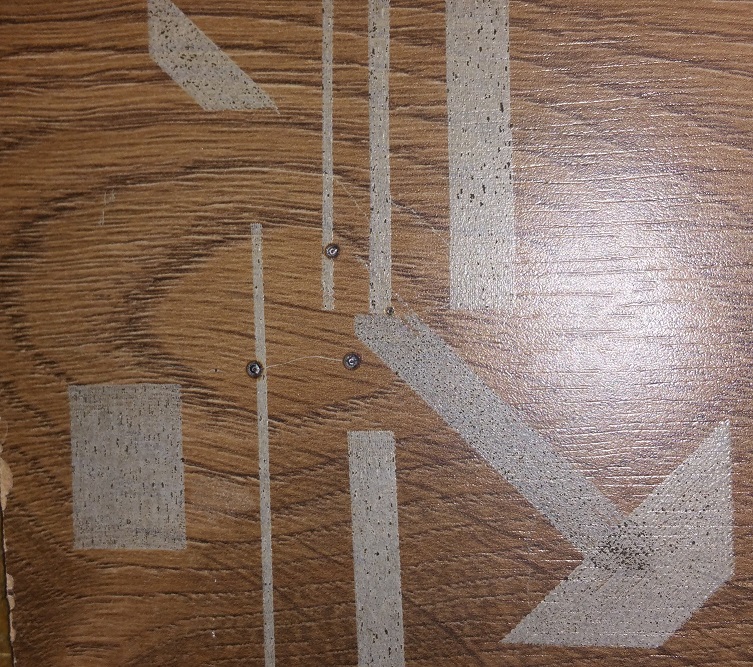
Hi so i have changed min pover to 200 and max to 210 and its start burning but as not expected
it looks like laser never go off its just cuts square not image
see attached ?
Is that me missing something here or its jus G-code not right?
Regards
Edited 1 time(s). Last edit at 08/30/2016 03:41PM by rastaman46.
it looks like laser never go off its just cuts square not image
see attached ?
Is that me missing something here or its jus G-code not right?
Regards
Edited 1 time(s). Last edit at 08/30/2016 03:41PM by rastaman46.
|
Re: TTL modulation help needed August 30, 2016 04:34PM |
Registered: 7 years ago Posts: 64 |
|
Re: TTL modulation help needed August 30, 2016 04:43PM |
Admin Registered: 16 years ago Posts: 13,884 |
... I can't correlate the burnt traces to the image - can you post a piece of your G-code, to see, what is sent to the firmware?
If your laser-driver has only binary TTL-input, it can't handle analogue voltages, but it should burn the black areas in the image, as they will give values above the threshold voltage.
Can you measure the output voltage and/or the pulses with a scope or DSO?
Viktor
--------
Aufruf zum Projekt "Müll-freie Meere" - [reprap.org] -- Deutsche Facebook-Gruppe - [www.facebook.com]
Call for the project "garbage-free seas" - [reprap.org]
|
Re: TTL modulation help needed August 31, 2016 04:58AM |
Registered: 9 years ago Posts: 93 |
|
Re: TTL modulation help needed August 31, 2016 09:22AM |
Registered: 9 years ago Posts: 93 |
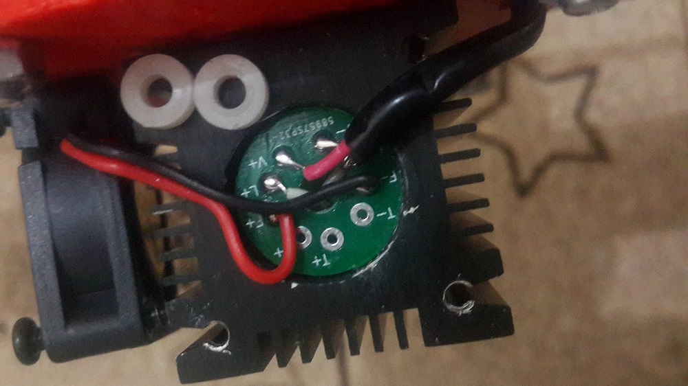
On laser side I got this
And behind fan there is PCB to connect fan /main power and have writing TTL+ / TTL-
Is here me trying to do something crazy or jus me gone crazy
Regards
Quote
Wavelength: 445nm (Blue)
Power: correspondence course 2500mW
Operating voltage: 12V (DC)
Working current: <1A
Idemitsu form: dot
Lens Material: dedicated optical coated glass
Cooling: Forced air
Shell material: aluminum anodized black
Input: 2.1 / 5.5 DC seat
And behind fan there is PCB to connect fan /main power and have writing TTL+ / TTL-
Is here me trying to do something crazy or jus me gone crazy
Regards
|
Re: TTL modulation help needed August 31, 2016 10:25AM |
Admin Registered: 16 years ago Posts: 13,884 |
... could be, you're driving your laser not with TTL, but by switching the power ON/OFF, what's normally a really bad idea!
If the solder pads labelled [T+] [T-] are the TTL-input, then you should control it here with connecting GND to [T-] and your +5V-PWM-output to [T+].
But as this is one of this cheapish chinese driver boards, there could be a totally different circuitry behind, so you have to extract the complete electronic, to check it ... or get some more useful infos from the vendor ...
Viktor
--------
Aufruf zum Projekt "Müll-freie Meere" - [reprap.org] -- Deutsche Facebook-Gruppe - [www.facebook.com]
Call for the project "garbage-free seas" - [reprap.org]
|
Re: TTL modulation help needed August 31, 2016 11:32AM |
Registered: 9 years ago Posts: 93 |
|
Re: TTL modulation help needed August 31, 2016 11:47AM |
Registered: 9 years ago Posts: 93 |
|
Re: TTL modulation help needed August 31, 2016 01:54PM |
Registered: 11 years ago Posts: 1,049 |
It appears that you just have a laser head?
What brand laser?
ask seller to sell you a driver for laser.

Usually
12V high current main supply to laser --- conditioned down to 3.3v constant current diode supply
and
a trigger circuit to turn diode ON / OFF properly
forcing the diode supply ON / OFF NOT the way to do it.
What brand laser?
ask seller to sell you a driver for laser.
Usually
12V high current main supply to laser --- conditioned down to 3.3v constant current diode supply
and
a trigger circuit to turn diode ON / OFF properly
forcing the diode supply ON / OFF NOT the way to do it.
|
Re: TTL modulation help needed August 31, 2016 03:00PM |
Admin Registered: 16 years ago Posts: 13,884 |
... the chines cloners often copy electronics without knowing exactly, what it's for ... and so the description can be miraculous too
It could be, this "2.1/5.5V DC" is the used TTL-level -- below 2.1V it would read LOW, above and to max. 5.5V it would read HIGH ... and above 5.5V it will burn.
But this is only guessed - get better infos or strip down the module and try to identify the correct inputs ...
Viktor
--------
Aufruf zum Projekt "Müll-freie Meere" - [reprap.org] -- Deutsche Facebook-Gruppe - [www.facebook.com]
Call for the project "garbage-free seas" - [reprap.org]
|
Re: TTL modulation help needed August 31, 2016 03:53PM |
Registered: 9 years ago Posts: 93 |
|
Re: TTL modulation help needed August 31, 2016 03:56PM |
Registered: 9 years ago Posts: 93 |
|
Re: TTL modulation help needed August 31, 2016 04:06PM |
Admin Registered: 16 years ago Posts: 13,884 |
... try to identify the circuit - if there is some means of controlling, then you need the correct specs and input values.
If it's only a constant current (CC) module, the the T+/T- inputs will do nothing - but then, if it's a simple CC, you can switch the 12V with an external 12V driver, as if it were a TTL input.
But best would be to remove the actual driver and use a better one, suited and documented for "real life" use ...
Viktor
--------
Aufruf zum Projekt "Müll-freie Meere" - [reprap.org] -- Deutsche Facebook-Gruppe - [www.facebook.com]
Call for the project "garbage-free seas" - [reprap.org]
|
Re: TTL modulation help needed August 31, 2016 04:52PM |
Registered: 9 years ago Posts: 93 |
Thanks for reply
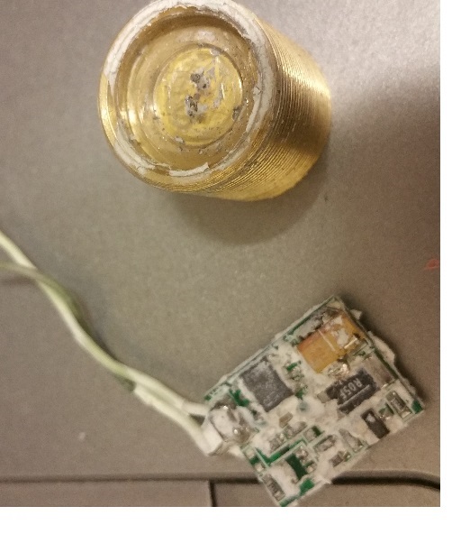
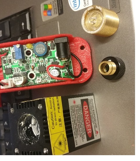
So i got it all apart now see attached (I totally destroyed module but i dont care coz i managed to remove led safely )
and i have attached picture with all i got left can i make something with it or i need to buy some more stuff??
btw t+ go nowhere its just there
Regards
So i got it all apart now see attached (I totally destroyed module but i dont care coz i managed to remove led safely )
and i have attached picture with all i got left can i make something with it or i need to buy some more stuff??
btw t+ go nowhere its just there
Regards
|
Re: TTL modulation help needed August 31, 2016 07:11PM |
Admin Registered: 16 years ago Posts: 13,884 |
... the previously "embedded" module seems to be a simple constant current driver, without any other controlling option.
The circuit in the red plastic housing seems to be one of the typical laserdiode drivers with TTL input, but with presoldered wires instead of plugs - here is one of this types:
Laser-driver
Was this driver with your lased-head?
Normally you have either a fix-current CC-driver in your diode head, or an adjustable driver like the last one - not both
Viktor
--------
Aufruf zum Projekt "Müll-freie Meere" - [reprap.org] -- Deutsche Facebook-Gruppe - [www.facebook.com]
Call for the project "garbage-free seas" - [reprap.org]
|
Re: TTL modulation help needed August 31, 2016 07:25PM |
Admin Registered: 16 years ago Posts: 13,884 |
... on second thought -- could it be, that the "embedded" module is only the driver for the fan, and the laser-diode is only connected to the bigger external circuit?
Then this would be the typical assembly and the TTL-input is on the external module, not on the T+/T- pins inside the laser-head.
If so, then all laser power controlling was done with the external module and the laser head isn't running with 12V, but with around 4V and the current set with the blue potentiometer.
Viktor
--------
Aufruf zum Projekt "Müll-freie Meere" - [reprap.org] -- Deutsche Facebook-Gruppe - [www.facebook.com]
Call for the project "garbage-free seas" - [reprap.org]
|
Re: TTL modulation help needed August 31, 2016 09:04PM |
Registered: 11 years ago Posts: 1,049 |
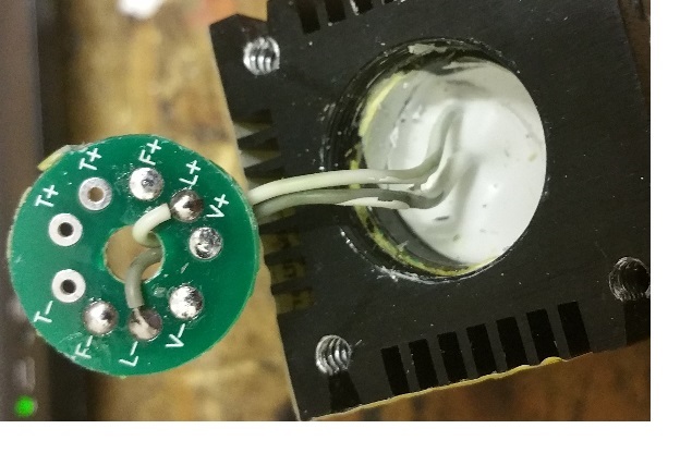
Not totally destroyed -- just needs to be soldered together
On your
20160323030418_93756.jpg
F-, F+ connected to fan
L-, L+ connected to laser diode
V-, V+ voltage supply
Where was the board in laser driver pix located?
What were grey and white wires connected to?
Where did circuit board on red plastic mount come from?
Stop jerkin us around and just tell us the driver on the red board
was in box you never unwrapped and used?
|
Re: TTL modulation help needed August 31, 2016 10:26PM |
Registered: 9 years ago Posts: 346 |
Hey,
The last one is your laser driver. The one with a trimpot and a big inductor. Mine is the exact same. Mine does the exact same behavior when controlled via "standard" PWM from an Arduino.
The problem is simply that you are running the TTL input too fast. You can't switch at the "standard" speeds that your Arduino controller outputs. If it goes too fast for the TTL input on the driver can't keep up.
It is very possible that you can't get the switching speeds that you want in the end.
It is my impression that our Chinese friends have designed this "TTL" input to be for controlling the laser On/Off only- So not for use for dimming while burning. It is actually good that it has this feature because otherwise you have to cut power when turning On/Off and that has all sorts of bad effects on in-swings and so forth.
This is as far as I have gotten (determined why TTL will not work).
Personally my next step would have been to try and put an Arduino between the G-code interpreter (RAMPS) and the laser driver. Have that Arudino send the PWM at a much slower rate. See here how to adjust the PWM form:
[playground.arduino.cc]
BUT I have abandoned that project. As it happens, I have connected a device to measure current (A) from that Chinese driver and it is really bad. Fluctuating +-0.1A easily. While for pure burning that doesn't matter much , it does matter a lot if you want to control the exact dimness. So the fact that the driver can't keep stable current and it can't work fast TTL kinda tells me this is not the driver you want to use for exact dimming operations.
Edited 1 time(s). Last edit at 08/31/2016 10:37PM by LarsK.
|
Re: TTL modulation help needed August 31, 2016 10:46PM |
Registered: 9 years ago Posts: 346 |
Hmm, my post sounded very negative.
Heads-up, the driver is fine for a lot of stuff. This week project:
LINK TO PHOTO
Double sided PCB for installation on my hot-end with power and Ethernet cable for signals. All made via VDX etching method and our Chinese laser driver using the TTL signal to control when it is burning or not. M42 P11 S255 and S0 respectively.
|
Re: TTL modulation help needed September 01, 2016 03:25AM |
Registered: 9 years ago Posts: 93 |
Thanks for reply
Yes that little board with white stuff round it was inside
I have purchased this [www.aliexpress.com] separate to run on TTL that what seller refer me to.That why I got lost on this could not get it to work.
Can I use this driver to drive diode now? or I need something different?
Regards
Yes that little board with white stuff round it was inside
I have purchased this [www.aliexpress.com] separate to run on TTL that what seller refer me to.That why I got lost on this could not get it to work.
Can I use this driver to drive diode now? or I need something different?
Regards
|
Re: TTL modulation help needed September 01, 2016 03:31AM |
Registered: 9 years ago Posts: 93 |
Thanks for reply
Driver in red box was purchased separate to run TTL
Seller refer me to this to run TTL (Looks like he have no idea what he selling)
Laser was 12DC with cc-driver built in (He description on laser isn't clear at all)
[www.aliexpress.com]
And he told me I need driver to run TTL refer me to this
[www.aliexpress.com]
Regards
|
Re: TTL modulation help needed September 01, 2016 04:47AM |
Admin Registered: 16 years ago Posts: 13,884 |
... OK, now it's a bit more clear ...
Your laser-head was previously only driven with a CC-driver (constant current) - but the 2500mW is not so clear either - there are actualy 445nm-laserdiodes with 1W, 1,6W, 2W, 3,5W and 6W available.
So the 2,5W is either an "overdriven" 2W-diode, or he gives not the optical output, but the drawn power -- so the laserdiode could be even a 1W-diode optically, that draws 2,5W power from the driver
Your big driver is the corret one for TTL-driving.
Before connecting it to the diode, you should define the correct current level.
For this you must ensure, which laserdiode you have - either a 2W-diode with 1.7A max, or a 1W-diode with 1A max.
Then you connect the laserdiode-output to a 5Watt-resisitor with 0,1 Ohm and adjust the current through the resistor to the max. current you want drive your diode with.
You measure the current either with an Ampere-meter connected in series to the resistor, or by measuring the voltage across the resisitor and calculating the current with the formula:
I = U/R (I in Amperes, U in Volts, R in Ohms)
-- with a 0,1Ohm resisistor and measured voltage of let's say 150 Millivolts (=0,15V) this will give you a current of 1,5 Amperes ...
Edited 1 time(s). Last edit at 09/01/2016 04:48AM by VDX.
Viktor
--------
Aufruf zum Projekt "Müll-freie Meere" - [reprap.org] -- Deutsche Facebook-Gruppe - [www.facebook.com]
Call for the project "garbage-free seas" - [reprap.org]
|
Re: TTL modulation help needed September 01, 2016 05:01AM |
Registered: 9 years ago Posts: 93 |

Sorry, only registered users may post in this forum.