Making PCB's with a diodelaser
Posted by VDX
|
Re: Making PCB's with a diodelaser July 28, 2014 08:44AM |
Admin Registered: 16 years ago Posts: 13,884 |
... here some 'laser-fretwork' - first a flying buttress (??? - in German "Schwibbogen) from Dresden:
... and a tempel-puzzle:
Edited 1 time(s). Last edit at 07/28/2014 08:45AM by VDX.
Viktor
--------
Aufruf zum Projekt "Müll-freie Meere" - [reprap.org] -- Deutsche Facebook-Gruppe - [www.facebook.com]
Call for the project "garbage-free seas" - [reprap.org]


... and a tempel-puzzle:


Edited 1 time(s). Last edit at 07/28/2014 08:45AM by VDX.
Viktor
--------
Aufruf zum Projekt "Müll-freie Meere" - [reprap.org] -- Deutsche Facebook-Gruppe - [www.facebook.com]
Call for the project "garbage-free seas" - [reprap.org]
|
Re: Making PCB's with a diodelaser July 28, 2014 02:55PM |
Registered: 10 years ago Posts: 814 |
|
Re: Making PCB's with a diodelaser July 30, 2014 04:15PM |
Registered: 10 years ago Posts: 143 |
|
Re: Making PCB's with a diodelaser July 30, 2014 04:21PM |
Admin Registered: 16 years ago Posts: 13,884 |
... I've done this first with a fibercoupled 9W@975nm IR-diode and last with a 2W@445nm diode.
For focussing of the IR-diode I've found aspheric PMAA-lenses, the 445nm-diode is focussed with one of the common collimators.
First paint the PCB black, then engrave the isolation contures of the tracks, then etch the freed copper ... and last remove the paint and drill the bores ...
Viktor
--------
Aufruf zum Projekt "Müll-freie Meere" - [reprap.org] -- Deutsche Facebook-Gruppe - [www.facebook.com]
Call for the project "garbage-free seas" - [reprap.org]
|
Re: Making PCB's with a diodelaser August 01, 2014 02:42AM |
Registered: 10 years ago Posts: 143 |
Do you really need 2W to "burn" the blackened PCBs? THat is a lot...
And why do you need to focus the laser? Is it not powerful enough to use the laser "as is"?
What setup have you been using? I saw on the earlier pages, that you seem to have built your own driver...
Are there any details on your setup? On the exact laser used, how it is fitted to the reprap, how is the focussing part done, etc?
Thanks
|
Re: Making PCB's with a diodelaser August 01, 2014 03:49AM |
Admin Registered: 16 years ago Posts: 13,884 |
... the black paint can be removed with lower power too, but then you have to draw much slower and/or with several passes, so this would need much more time.
The laserdiode emits in a strong diverging cone, so for removing/evaporating the paint without (re-)focussing optics you'll have to open the case and place the diode direct onto the surface ... what will kontaminate the emitter window and wreck the diode instantly.
With the lens you 'refocus' the emitting area onto the surface with some ten millimeters distance, so you can remove the smokes before they'll touch/kontaminate the optics.
Yes, I'm building my own drivers with regulating constant currents from some milliamperes to some ten amperes and PWM-switching the current to the diodes.
The first driver versions with LM317 or LM338 as constant-current regulators are shown here: [www.reprap.org]
The actual versions with OPAmp+MOSFETs are classified ...
Viktor
--------
Aufruf zum Projekt "Müll-freie Meere" - [reprap.org] -- Deutsche Facebook-Gruppe - [www.facebook.com]
Call for the project "garbage-free seas" - [reprap.org]
|
Re: Making PCB's with a diodelaser November 14, 2014 09:38PM |
Registered: 10 years ago Posts: 17 |
Hello Viktor
What a great project. Over the years I have struggled to make circuit boards using mainly the toner transfer method and designing the board using Eagle. A while back I built a 3D printer and seeing your project makes me think that It may be possible to modify the printer to accept the Laser diode. Could you suggest some suitable software to convert Eagle files and printing them on my 3D printer.
Thanks:
|
Re: Making PCB's with a diodelaser November 15, 2014 09:37AM |
Admin Registered: 16 years ago Posts: 13,884 |
... I was using different outline-ulp's with Eagle, but then changed to Target, as it's direct exporting NC-codes and isn't limited in size as with Eagle ...
Viktor
--------
Aufruf zum Projekt "Müll-freie Meere" - [reprap.org] -- Deutsche Facebook-Gruppe - [www.facebook.com]
Call for the project "garbage-free seas" - [reprap.org]
Viktor
--------
Aufruf zum Projekt "Müll-freie Meere" - [reprap.org] -- Deutsche Facebook-Gruppe - [www.facebook.com]
Call for the project "garbage-free seas" - [reprap.org]
|
Re: Making PCB's with a diodelaser November 15, 2014 05:22PM |
Admin Registered: 16 years ago Posts: 13,884 |
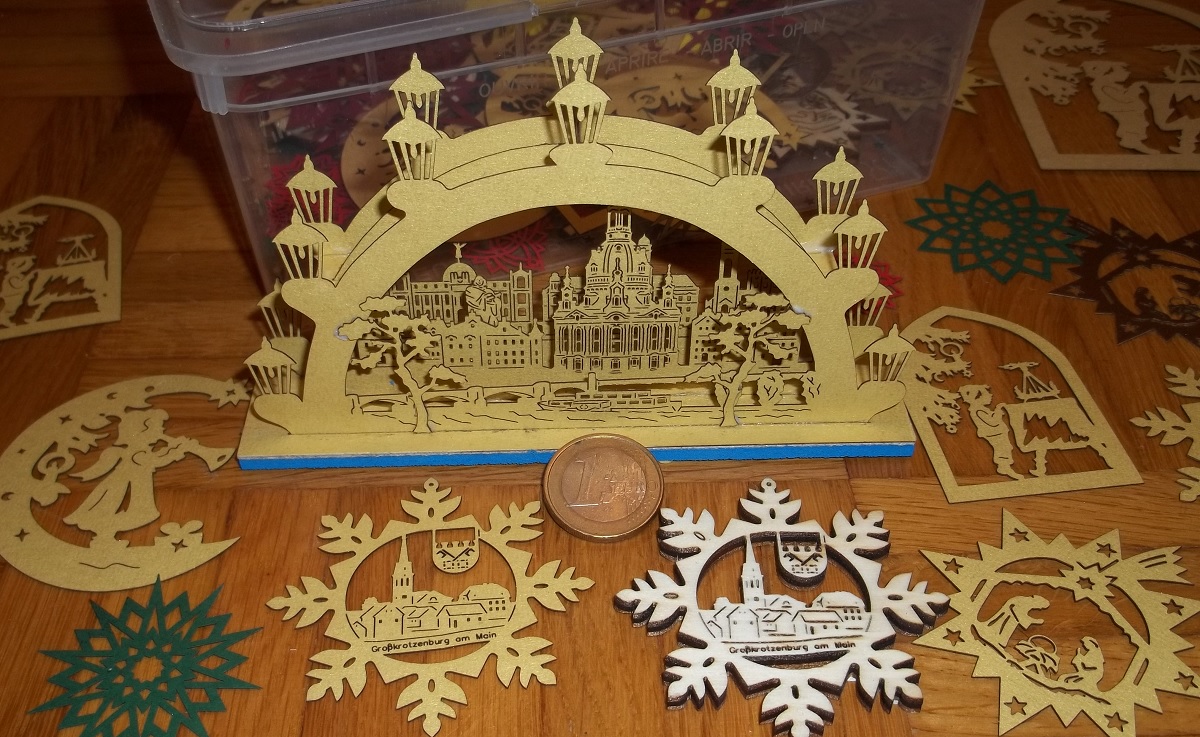
... I've made some more Christmas-deko (attached more in detail):
Viktor
--------
Aufruf zum Projekt "Müll-freie Meere" - [reprap.org] -- Deutsche Facebook-Gruppe - [www.facebook.com]
Call for the project "garbage-free seas" - [reprap.org]

Viktor
--------
Aufruf zum Projekt "Müll-freie Meere" - [reprap.org] -- Deutsche Facebook-Gruppe - [www.facebook.com]
Call for the project "garbage-free seas" - [reprap.org]
|
Re: Making PCB's with a diodelaser November 16, 2014 04:15PM |
Admin Registered: 16 years ago Posts: 13,884 |
... my wife wants a bit more atmosphere ...
Viktor
--------
Aufruf zum Projekt "Müll-freie Meere" - [reprap.org] -- Deutsche Facebook-Gruppe - [www.facebook.com]
Call for the project "garbage-free seas" - [reprap.org]

Viktor
--------
Aufruf zum Projekt "Müll-freie Meere" - [reprap.org] -- Deutsche Facebook-Gruppe - [www.facebook.com]
Call for the project "garbage-free seas" - [reprap.org]
|
Re: Making PCB's with a diodelaser January 26, 2015 04:44AM |
Registered: 9 years ago Posts: 1,011 |
Very nice work viktor, It'm realy impressed by the results. Laser is to me a very strange world I don't understand yet. Congratulations.
Collective intelligence emerges when a group of people work together effectively. Prusa i3 Folger (A lot of the parts are wrong, boring !)
Collective intelligence emerges when a group of people work together effectively. Prusa i3 Folger (A lot of the parts are wrong, boring !)
|
Re: Making PCB's with a diodelaser January 26, 2015 05:35AM |
Admin Registered: 16 years ago Posts: 13,884 |
... thanks!
My first laser-impression was on a trade-show in Leipzig (MusterMesse Leipzig) around 1974, where a medium sized box emitted a really bright green beam with maybe 10mm diameter ... and they sometimes put a match into the beam to light it
The beam ended simply in a black target ... but beside was a big white brick with a molten hole of maybe 40mm diameter in it
From then on (powerfull!) lasers were one of my targets ... and maybe ten years later the next 'impression-activated' goal was molecular microtech
Edited 1 time(s). Last edit at 01/26/2015 05:37AM by VDX.
Viktor
--------
Aufruf zum Projekt "Müll-freie Meere" - [reprap.org] -- Deutsche Facebook-Gruppe - [www.facebook.com]
Call for the project "garbage-free seas" - [reprap.org]
|
Re: Making PCB's with a diodelaser February 18, 2015 06:08PM |
Registered: 9 years ago Posts: 3 |
Hi,
I thought it is better to post it here instead of starting a new topic.
I'm having problems with laser paint etching for PCBs.
I made a 1W 445 nm laser (Casio 5.6 mm diode) with 3 element lens, attached it to my CNC 3020T machine and connected TTL input to a BeagleBone Black GPIO output (I use LinuxCNC/Machinekit).
Then I modified FlatCAM a bit to generate isolation milling g-codes, but instead of moving Z axis it generates M62-M65 g-codes (digital output control). All working very well, although it takes quite a bit of time to laser a PCB, as my machine is not very fast.
The biggest issue I have is with the paint. I've tried a few, from the cheapest black spray paint (1 GBP at one pound store) to high temperature oven & exhaust paint, to line marking paint (fast drying but ugly drying with bubbles etc) to painting a PCB with a wide tip black marker.
Pretty much every time the laser doesn't go all the way through the paint leaving a thin layer that blocks the etchant. I've tried different feedrates (from 200 mm/min to 1500 mm/min), that mostly affects the thickness of the line. I've tried some air assist, blowing air from a compressor from one corner of the PCB - not a huge improvement. I've tried cleaning with isopropanol, but for some paints it completely ruins it, for others it is not so aggresive but still it smears the paint.
The most success I had was with water + window cleaner liquid (sufracant) in an ultrasonic cleaner plus some gentle brushing. Unfortunately, this method is not bulletproof (and it is still possible to destroy the valid paint layer), there are still places with this nasty paint residue. Some of these can be etched but it requires very long etching and in effect the remaining 80% of the board is overetched so I have very narrow traces or broken traces (but at the same time in the most stubborn places have shorts between traces).
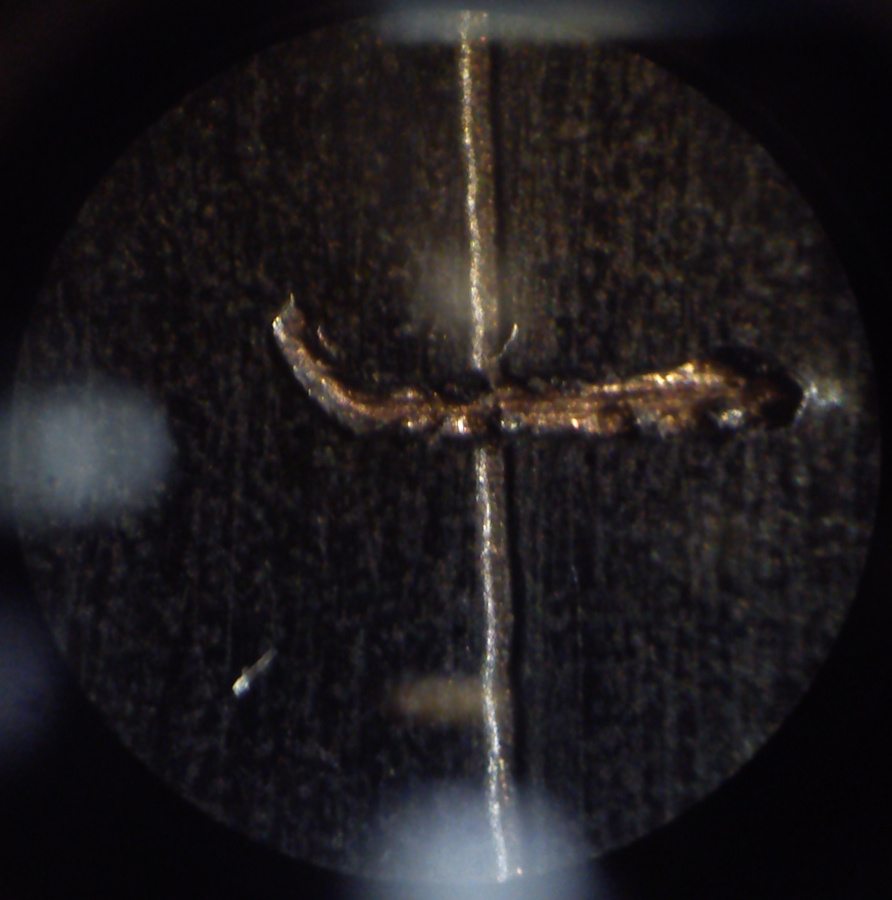
I've attached a 40x microscope image of a lasered line (vertical) and a manually scribed line (horizontal).
I don't know what else to try. I suspect that the copper obviously is a good heat conductor and laser reflector at the same time and at some depth into the paint the beam is weakened by both these effects (not hot enough spot and remaining light reflected) before it can go all the way through. I wondered if using RepRap heated bed would help. If the PCB is at, let's say 80 deg, the laser beam has less temperature difference to create at the spot.
Any suggestions?
I thought it is better to post it here instead of starting a new topic.
I'm having problems with laser paint etching for PCBs.
I made a 1W 445 nm laser (Casio 5.6 mm diode) with 3 element lens, attached it to my CNC 3020T machine and connected TTL input to a BeagleBone Black GPIO output (I use LinuxCNC/Machinekit).
Then I modified FlatCAM a bit to generate isolation milling g-codes, but instead of moving Z axis it generates M62-M65 g-codes (digital output control). All working very well, although it takes quite a bit of time to laser a PCB, as my machine is not very fast.
The biggest issue I have is with the paint. I've tried a few, from the cheapest black spray paint (1 GBP at one pound store) to high temperature oven & exhaust paint, to line marking paint (fast drying but ugly drying with bubbles etc) to painting a PCB with a wide tip black marker.
Pretty much every time the laser doesn't go all the way through the paint leaving a thin layer that blocks the etchant. I've tried different feedrates (from 200 mm/min to 1500 mm/min), that mostly affects the thickness of the line. I've tried some air assist, blowing air from a compressor from one corner of the PCB - not a huge improvement. I've tried cleaning with isopropanol, but for some paints it completely ruins it, for others it is not so aggresive but still it smears the paint.
The most success I had was with water + window cleaner liquid (sufracant) in an ultrasonic cleaner plus some gentle brushing. Unfortunately, this method is not bulletproof (and it is still possible to destroy the valid paint layer), there are still places with this nasty paint residue. Some of these can be etched but it requires very long etching and in effect the remaining 80% of the board is overetched so I have very narrow traces or broken traces (but at the same time in the most stubborn places have shorts between traces).
I've attached a 40x microscope image of a lasered line (vertical) and a manually scribed line (horizontal).
I don't know what else to try. I suspect that the copper obviously is a good heat conductor and laser reflector at the same time and at some depth into the paint the beam is weakened by both these effects (not hot enough spot and remaining light reflected) before it can go all the way through. I wondered if using RepRap heated bed would help. If the PCB is at, let's say 80 deg, the laser beam has less temperature difference to create at the spot.
Any suggestions?
|
Re: Making PCB's with a diodelaser February 18, 2015 06:55PM |
Admin Registered: 16 years ago Posts: 13,884 |
... I'm cleaning with soap+water and a soft brush.
What's your focal distance and spot size or line width? - ye shorter the distance from the last lens to the surface, the higher the energy density and "cutting efficiency" -- my best distances are around 20mm for engraving and max. 40mm for cutting ... the resulting focus diameters are then like something around 0.05 and 0.08mm ...
You can engrave two parallel lines overlapping with maybe 30% of the linewidth for better etching ...
Viktor
--------
Aufruf zum Projekt "Müll-freie Meere" - [reprap.org] -- Deutsche Facebook-Gruppe - [www.facebook.com]
Call for the project "garbage-free seas" - [reprap.org]
|
Re: Making PCB's with a diodelaser February 21, 2015 01:01AM |
Registered: 9 years ago Posts: 125 |
I immediately dropped the idea of just generating the isolation cuts, since it basically ignores all the spacing rules between the lines (ie, there's not much air between copper lines that way).
So instead, I paint the non-copper areas. That way you eliminate a lot more paint from the board and making it easier for the etchant to reach the copper.
As for the paint, I just bought a random matte black water-based spray.
[1drv.ms]
On the images, it's visible that I set the tool diameter a bit too low, so it ate a bit too much on the smaller vertical trace (had to replace it with a small wire).
I only used tissue paper for cleaning the traces, no chemicals.
Edited 1 time(s). Last edit at 02/21/2015 01:07AM by Mikk36.
|
Re: Making PCB's with a diodelaser February 21, 2015 05:04PM |
Admin Registered: 16 years ago Posts: 13,884 |
... depending on the used program, the generation of isolation lines can be adjusted in various ways including distance rules, line-widths or freeing specified areas completely.
I'm using the free version of Target, which is exporting complete NC-programs for my CNC-mill/-laserengraver or as common DXF or G-code ...
Viktor
--------
Aufruf zum Projekt "Müll-freie Meere" - [reprap.org] -- Deutsche Facebook-Gruppe - [www.facebook.com]
Call for the project "garbage-free seas" - [reprap.org]
|
Re: Making PCB's with a diodelaser February 21, 2015 05:28PM |
Registered: 9 years ago Posts: 3 |
Thanks Viktor,
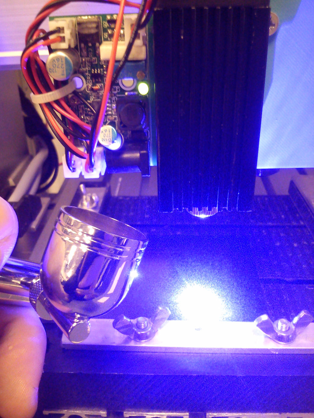
I suspect focusing too. I attach a photo of my typical setup (here with some air from a compressor blowing over the PCB ).
The laser is surely closer to the 40 mm distance than 20 mm. I'll try your suggestions tomorrow.
As my setup is not permanent (I attach the laser when I need it) I always have to refocus it, but often I struggle to see "is the dot smallest possible yet or not". Once I tried doing this on reduced power (I think 100-200mA instead of 1A), but this requires some rewiring (multimeter) every time and even at low power level the laser burns targets (e.g. a piece of paper) that would be suitable to see the dot.
What I do now that sort of works is that I put thin part of my machinist square (I think it's 1 mm flat steel) in the place where I normally clamp a PCB. The steel is reflective, but it's not a mirror polish and laser doesn't affect it. Still, it is hard to say if the spot is 50-80 um (as you mention) or ~120 um (I measured that once). Also I use the sharp corner of the steel to set 0,0 point.
Do you know a proper methodical way to focus the laser to its tightest spot?
@Mikk36
How do you "paint non-copper areas"? FlatCAM, in addition to generating isolation milling paths, can generate this, but it does this by some space filling curves. Isolation milling takes ages on my machine and I suspect this approach would take even longer (much more lines to travel).
I thought about writing some code that would generate raster based laser etching. Big CO2 lasers can do that. My idea is to render Gerber geometry into a bitmap, setting a resolution so one pixel corresponds to 50 um dot and then, line by line generate a X axis linear movement with M62 & M63 codes to turn the laser on and off at specified points along a line.
I'm not sure it would be faster (100x100 mm PCB would mean 2000 lines along Y axis, each let's say at my machine's max speed 33 mm/s, so that's 3 seconds, but we need to add some acceleration and deceleration, let's say 5 sec, 2000 lines means then 167 minutes).
Also, the depth of laser ablation might be poor and it may be even more difficult to remove this paint residue.
|
Re: Making PCB's with a diodelaser February 21, 2015 06:08PM |
Admin Registered: 16 years ago Posts: 13,884 |
... for coarse measuring the focus distance I'm using a black target to reduce blinding and some smoke to make the beam visible, so you can see the thinnest beam zone.
You can engrave some lines on black anodized aluminium to get the thinnest possible linewidths in X and Y when positioned in the optimal distance - then make a measure with the distance from surface to diode housing, to simply set this measure on the surface and adjust the focus by adjusting the height ...
Viktor
--------
Aufruf zum Projekt "Müll-freie Meere" - [reprap.org] -- Deutsche Facebook-Gruppe - [www.facebook.com]
Call for the project "garbage-free seas" - [reprap.org]
|
Re: Making PCB's with a diodelaser February 22, 2015 11:33AM |
Registered: 9 years ago Posts: 125 |
This is how I do it (with 750 mm/min feedrate):
Select gerber file, create non-copper regions geometry.
Select the noncopper object
And start clicking on the Generate button in the Paint Area section
and then the white areas on the display on the right until every one I need is selected.
After everything is generated, you select all the paint objects and join them from the edit menu
which will get you a Combo object
From there, you generate the CNC Job
After which you can finally export the g-code

Select gerber file, create non-copper regions geometry.

Select the noncopper object

And start clicking on the Generate button in the Paint Area section

and then the white areas on the display on the right until every one I need is selected.

After everything is generated, you select all the paint objects and join them from the edit menu

which will get you a Combo object

From there, you generate the CNC Job

After which you can finally export the g-code
|
Re: Making PCB's with a diodelaser February 22, 2015 11:35AM |
Registered: 9 years ago Posts: 125 |
Also, you should really use a PWM-input capable driver for the LED, that way you can easily reduce the output power of the laser in order to make focusing easier without touching the potentiometers each time.
This also makes it possible to do raster-engraving (variable power, constant speed).
Edited 1 time(s). Last edit at 02/22/2015 11:36AM by Mikk36.
This also makes it possible to do raster-engraving (variable power, constant speed).
Edited 1 time(s). Last edit at 02/22/2015 11:36AM by Mikk36.
|
Re: Making PCB's with a diodelaser February 22, 2015 11:59AM |
Registered: 9 years ago Posts: 3 |
@Mikk36:
that's exactly what I meant by "space filling curves" - the usage of non-copper regions and paint area in FlatCAM. The problem is that it generates even more G-code lines and arcs (and a lot of accelerations and decelerations) that would take even longer than isolation milling alone. This might be fine for a tiny simple PCB, like the one in your example, but it is an absolute nightmare for more complex boards or boards that are >= 100x100mm, takes ages (hours for double-sided) and in my current setup I cannot run the laser unsupervised.
You are right about the driver. For now this is my initial setup made out of parts from ebay and odicforce and I use TTL control only as on/off. With this setup, intended as a bootstrap, when I finally get more reliable PCBs I want to build a driver for M140 (2W) diode with DAC current control, TTL input and TEC & fan control, communicating over RS-485 from the main CNC controller.
|
Re: Making PCB's with a diodelaser February 23, 2015 02:38PM |
Registered: 10 years ago Posts: 19 |
|
Re: Making PCB's with a diodelaser March 02, 2015 07:42AM |
Registered: 9 years ago Posts: 9 |
i have a chinese 5W 808nm diode and i'm focusing the beam with an microscope okular.. the focus distance is about 120mm and i can engrave wood like it was nothing. so i decided to try this method for making PCB's. i couldn't fidn a black spray paint in the house but i did find a dark blue color... so i sprayed the PCB and did a test... the laser did leave marks in the pcb but it was not burned... so can you tell me if its the color (too bright) or the focusing optics.... i know some basic stuff about lasers. but it seem the lens does a good job because wood engraving works like a charm...
Thank you!
Thank you!
|
Re: Making PCB's with a diodelaser March 02, 2015 07:55AM |
Registered: 9 years ago Posts: 125 |
|
Re: Making PCB's with a diodelaser March 02, 2015 08:15AM |
Admin Registered: 16 years ago Posts: 13,884 |
... diffrent colours are different in behaviour, but with the IR-diodes it's mostly the absorption rates of the paint, so best with really dark pigments - paint a piece of glass and look through to check the remaining transparency ...
Viktor
--------
Aufruf zum Projekt "Müll-freie Meere" - [reprap.org] -- Deutsche Facebook-Gruppe - [www.facebook.com]
Call for the project "garbage-free seas" - [reprap.org]
Viktor
--------
Aufruf zum Projekt "Müll-freie Meere" - [reprap.org] -- Deutsche Facebook-Gruppe - [www.facebook.com]
Call for the project "garbage-free seas" - [reprap.org]
|
Re: Making PCB's with a diodelaser March 03, 2015 01:35AM |
Registered: 9 years ago Posts: 9 |
|
Re: Making PCB's with a diodelaser March 03, 2015 02:35AM |
Admin Registered: 16 years ago Posts: 13,884 |
Quote
Tady
Viktor how did you paint yours? only one thin coat?
... yes - ye thinner, the better -- for this you'll need paints with really high pigment filling rates ...
Viktor
--------
Aufruf zum Projekt "Müll-freie Meere" - [reprap.org] -- Deutsche Facebook-Gruppe - [www.facebook.com]
Call for the project "garbage-free seas" - [reprap.org]
|
Re: Making PCB's with a diodelaser March 03, 2015 08:25AM |
Registered: 9 years ago Posts: 9 |
|
Re: Making PCB's with a diodelaser March 03, 2015 09:29AM |
Admin Registered: 16 years ago Posts: 13,884 |
... I've used different fast drying spray paints, as common for spraying RC-planes and -cars, but other paints for outdoor decoration use were OK too ... but again, prefer fast drying types!
Another 'good' spray paint was one, normally used for painting ovens and stovepipes, so heat resistant up to 800degC or 1200degC - here an example:
[www.amazon.de]
Viktor
--------
Aufruf zum Projekt "Müll-freie Meere" - [reprap.org] -- Deutsche Facebook-Gruppe - [www.facebook.com]
Call for the project "garbage-free seas" - [reprap.org]
|
Re: Making PCB's with a diodelaser March 04, 2015 01:50AM |
Registered: 9 years ago Posts: 9 |
I did a quick test with a common black fast drying spray-paint and this is what i got (attachment). It seem it worked. Inside the traces you can see that some of the pigment didn't go away. But i had to use speed of 55mm/min so the darn thing is veryyyyy slooow ... i don't know where i'm going wrong with this... the only possible reasons are... a.) i have a big problem with optics(??), or the diode is nog giving the power as it is rated for (2,2V(drop)@5A).
Anyway i ran out of HCL and H202 so i couldn't etch the board... i will try to get the ingredients today and see if the laser worked
Edited 1 time(s). Last edit at 03/04/2015 01:54AM by Tady.
Anyway i ran out of HCL and H202 so i couldn't etch the board... i will try to get the ingredients today and see if the laser worked
Edited 1 time(s). Last edit at 03/04/2015 01:54AM by Tady.


Sorry, only registered users may post in this forum.