Pick and Place toolhead, STL files included!
Posted by Gene Hacker
|
Pick and Place toolhead, STL files included! July 31, 2008 03:46AM |
Registered: 16 years ago Posts: 174 |
This new toolhead allow RepRap to manipulate surface mount components. If a milling head and solder paste dispenser could be added to RepRap then production of the required PCBs could be fully automated(except you'll still have to solder on the non SMT components).
How it works:
a small vacuum pump creates suction in the blunt tip needle to pick up SMT components and the gear motor rotates the component into the proper position.
Materials:
6 20 mm M3 cap screws
3 35 mm M3 cap screws
1 10 mm M2 screw, or whatever screw will couple with the shaft on the GM3 gear motor
1 18 gauge blunt tip dispenser needle
1 magnetic rotary encoder and magnet retrofitted GM3 gear motor
1 meter of 4 mm diameter aquarium tubing $0.43
a low vacuum pump, possibly a reversed aquarium air pump
Instructions:
1. connect the part named pnpdisk2 to the motor drive shaft
2. stick the 4 mm aquarium tubing into the blunt tip dispenser needle and put this into the part called pnpdisk1
3. attach pnpdisk1 to pnpdisk2 with the 20 mm M3 cap screws
4. attach the magnetic rotary encoder to the part called pnpclamp with 20 mm M3 cap screws
5. attach gear motor to clamp with 35 mm M3 cap screws
6. attach clamp to x carriage
How it works:
a small vacuum pump creates suction in the blunt tip needle to pick up SMT components and the gear motor rotates the component into the proper position.
Materials:
6 20 mm M3 cap screws
3 35 mm M3 cap screws
1 10 mm M2 screw, or whatever screw will couple with the shaft on the GM3 gear motor
1 18 gauge blunt tip dispenser needle
1 magnetic rotary encoder and magnet retrofitted GM3 gear motor
1 meter of 4 mm diameter aquarium tubing $0.43
a low vacuum pump, possibly a reversed aquarium air pump
Instructions:
1. connect the part named pnpdisk2 to the motor drive shaft

2. stick the 4 mm aquarium tubing into the blunt tip dispenser needle and put this into the part called pnpdisk1

3. attach pnpdisk1 to pnpdisk2 with the 20 mm M3 cap screws
4. attach the magnetic rotary encoder to the part called pnpclamp with 20 mm M3 cap screws

5. attach gear motor to clamp with 35 mm M3 cap screws
6. attach clamp to x carriage
|
Re: Pick and Place toolhead, STL files included! August 22, 2009 06:00PM |
Registered: 14 years ago Posts: 17 |
Did you ever see how a real industry grade pick and place robot works?
All the machines i've seen so far use some kind of camera where the toolhead moves over to measure the exact position of the part on the vacuum head before it gets placed onto the board. As far as i understood this is mainly needed for components that get delivered in tubes or trays, where the position of the component is not 100% guaranteed. For stuff that get delivered in belts, it depends on the type of belt, but usually the components have a little bit of play in the belt, so the camera is needed too. The only components i remember do not need a position feedback are the standard surface mount capacitors/resistors, as they are seated pretty tight in the belts.
Try to position a 0.5mm pitch circuit if it has a 0.5mm positional play when it gets picked up... you see the problem i'm referring to?
So, to really have a working SMD pick and place machine, you need a camera with enough resolution to measure the components position, analyze the picture and then compensate the target position to get a good result... good luck with that part of the project.
|
Re: Pick and Place toolhead, STL files included! August 23, 2009 08:14AM |
Registered: 15 years ago Posts: 59 |
You might be able to get away with some sort of optical gate. This would be an opto interrupter that the tip of the toolhead moved through. It could figure out the position of the part (or even if it was there at all) by the timing of when the light was blocked. This would take considerably less programming complexity than a camera would.
Frank Davies
Frank Davies
|
Re: Pick and Place toolhead, STL files included! August 23, 2009 04:29PM |
Registered: 14 years ago Posts: 17 |
Maybe you can hack a laser mouse and use that as a sensor. With the resolution these sensors have today i think you could get the precision high enough. Just an idea. Haven't really looked into the details and if these sensors got hacked for other applications already.
The optical gate would definately be cheaper and easyer to use, as long as you manage to get the precision needed.
Still, it will give you quite some work to use the feedback of whatever sensor you have. You basically have to build up a library including package dimensions of every footprint you want to use, and you have to have some kind of "feeder" where you can go pick up the components too.
So, the pick and place head as is can be a nice tool, but to really use it for an application, there is quite some more work to do.
|
Re: Pick and Place toolhead, STL files included! August 25, 2009 12:43AM |
Registered: 16 years ago Posts: 174 |
No, never seen how real pick and place machines work. Visual recognition of component parts would also automate things more, no need to carefully align parts in a parts tray. Might a webcam work?
Another option might be to use one of those cheap USB microscopes, the one I have has some fairly decent resolution.
Another option might be to use one of those cheap USB microscopes, the one I have has some fairly decent resolution.
|
Re: Pick and Place toolhead, STL files included! August 25, 2009 01:09AM |
Registered: 14 years ago Posts: 458 |
A real Pick and Place machine, grabs parts from a known orientation, and knows how many parts there are in the notches of the tape.
For example, if you got a MakerBot V2.3 driver board or !.2 Mobo, and noticed the holes next to the part in the tape, that is what is used for Pick and place machines.
An encoder in the head servo orientates the part before placing it onto the board, therefore it assumes that every part in the tape is the correct orientation already (sometimes there is a part that is the wrong way around).
what you'd need to do is have a feeder, calibratable to know how may parts there are per tick (hole in the side of the tape)
|
Re: Pick and Place toolhead, STL files included! August 25, 2009 06:38AM |
Registered: 17 years ago Posts: 550 |
this is important for industrial p'n'p systems;
but if it's intention is to be a reprap toolhead....?
Most of us wont order 5000 identical parts but just as much as we need to build what ever there is to build (plus two spares)
So we'll have many short tapes, if we get tapes at all, that is;
I often don't.
But since we don't have that many parts at all, we can manually feed the head,
and the head lays down the part to a known position on something like a rubber bed.
Or we can lay the parts onto the rubber bed directly, but then we need some visual recognition again...
'sid
but if it's intention is to be a reprap toolhead....?
Most of us wont order 5000 identical parts but just as much as we need to build what ever there is to build (plus two spares
)So we'll have many short tapes, if we get tapes at all, that is;
I often don't.
But since we don't have that many parts at all, we can manually feed the head,
and the head lays down the part to a known position on something like a rubber bed.
Or we can lay the parts onto the rubber bed directly, but then we need some visual recognition again...
'sid
|
Re: Pick and Place toolhead, STL files included! August 25, 2009 02:22PM |
Admin Registered: 16 years ago Posts: 13,884 |
... the simplest solution will be a webcam visualizing a spot on a pan- and XY-stage - e.g. a simple manually XY-stage with a rotating plate on it.
Then you put a part (or a hopper with more parts) in the focus, move and rotate the stage until the part is in the right position and orientation (maybe a crosshair on the screen) and start your pick'n'placer ...
Viktor
Then you put a part (or a hopper with more parts) in the focus, move and rotate the stage until the part is in the right position and orientation (maybe a crosshair on the screen) and start your pick'n'placer ...
Viktor
|
Re: Pick and Place toolhead, STL files included! August 25, 2009 06:35PM |
Registered: 17 years ago Posts: 550 |
Nice idea... I guess *kopfkratz*
Well, but since the part hopefully gets centered on the nozzle (a matter of precision) any non 90° orientation will get lost with that step, so no fancy 45° layouts possible
Do you remember that beautiful pick 'n placer from the cnc or robotik forum you mentioned some months ago? (can't even remember the forum unfortunately)
that's what we would need I guess
man that was fast...
'sid
|
Re: Pick and Place toolhead, STL files included! August 26, 2009 03:40AM |
Admin Registered: 16 years ago Posts: 13,884 |
Hi sid,
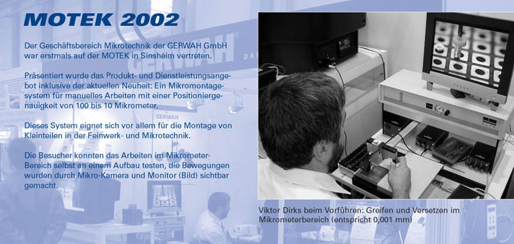
... some years ago i had to redesign a manually operated SMD-placer from Finetech into a camera-controlled microassembly system.
That was a really nice mechanical setup with two freerunning linear bars in X and Y where the toolhead with a (manually) controlled rotating vacuum-gripper (essential a syringe-tip with a small rubber-cone) is atached on the Y-axis.
With iron-strips atached to the sliders and running along solenoids you can 'freese' the actual position, so an aditional PZT-actuator could 'fineplace' and so ...
I simply adapted two adjustable 'finger'-cameras from front and side - atached an image where i'm placing some plastic-nibbles in an hole-array.
At home i have a similar but heavier and stiffer XY-slider-setup and all the adapters and cameras - so it wouldn't be a big problem to rebuild this system ...
Viktor
|
Re: Pick and Place toolhead, STL files included! January 13, 2010 06:09PM |
Check this DIY pick and place out: [www.youtube.com]
The guy used a little pit of known dimensions to center his parts. After picking up the part he bumps it against the edges of the pit which moves it on the needle. By doing this four times you can be guaranteed the part is centered with a great deal of accuracy. Bump against left X until the needle is at the edge of the pit, then bump against right X half the width of the part and it is now centered in X. Do the same for Y and you are centered.
Pretty clever, I thought.
|
Re: Pick and Place toolhead, STL files included! January 13, 2010 07:53PM |
Admin Registered: 17 years ago Posts: 1,791 |
Yup. It's mentioned in the other thread. I sent them a friendly email the other day, but I think they're too busy to work on it.
Gene Hacker's stuff at the top is cool, and we library gnomes should get in into the wiki promptly, using the "Generic" page as a model:
[objects.reprap.org]
Edited 1 time(s). Last edit at 01/13/2010 08:17PM by SebastienBailard.
Gene Hacker's stuff at the top is cool, and we library gnomes should get in into the wiki promptly, using the "Generic" page as a model:
[objects.reprap.org]
Edited 1 time(s). Last edit at 01/13/2010 08:17PM by SebastienBailard.
|
Re: Pick and Place toolhead, STL files included! January 13, 2010 08:47PM |
Admin Registered: 17 years ago Posts: 1,791 |
|
Re: Pick and Place toolhead, STL files included! January 29, 2010 04:31PM |
Registered: 14 years ago Posts: 49 |
I can't wait to see this tried out! Thanks for the heads up Sebastien - I've added this to the wiki:
[objects.reprap.org]
[objects.reprap.org]
|
Re: Pick and Place toolhead, STL files included! February 01, 2010 07:53AM |
Regarding a DIY p'n'p
I really cannot say how useful this comment will be, but herewith are links to an open-source c library pertaining to computer vision.
Download
[sourceforge.net]
Wiki
[opencv.willowgarage.com]
I feel obligated to immediately point out several implementation issues, wrt this software package:
1. Even though the software is written in c, the implementation is computationally more expensive than an atmega cpu can bear. Assumption.
2. A proof-of-concept would probably best be implemented on Mendel host, with Atmel cpu receiving trajectory information from host, after image processing on host has been completed. This requires the following software to be developed:
2.1. Host image processing software, using openCV libraries. When image processing is completed, execute path-planning to obtain prefered/optimal trajectory. If necessary, path-planning might include obstruction avoidance.
2.2. Interface specification- and implementation between host and RepRap/Mendel for trajectory (and orientation) commands.
2.3. Alteration/ Modification of Atmega CPU software to receive- and execute trajectory information.
2.4. The control-loop is closed with web-cam(s) watching the execution of trajectory path.
3. The current application under discussion, i.e. p'n'p, does not require near-real-time image processing throughput, so additional INTEL (tm) specific libraries that enhance calculations, will not be required. Assumption.
4. The library contains algorithms that are ideal for:
4.1. Component recognition. Shape recognition, in particular benefits HOUGH-transform, which is good to extract lines (circuit tracks), circles (pcb holes) and rectangles (SMT resistors, capacitors and other components). The algorithm also extracts orientation (obviously, for circles orientation would be redundant).
4.2. Speed tracking. To do this, the software first:
4.2.1. Extracts features from image , using Hessian matrix to detect "corners"
4.2.2. Tracks features in motion, using Kalman filter.
If you are interested in this, the download link provided above includes samples of the algorithms I mentioned. I have downloaded and played with these files already, and I fully intend to incorporate some computer-vision into my mendel when it is "completed".
Regards
Marius Botha,
Pretoria
South Africa
|
Re: Pick and Place toolhead, STL files included! February 02, 2010 11:20AM |
Admin Registered: 17 years ago Posts: 1,915 |
|
Re: Pick and Place toolhead, STL files included! February 03, 2010 04:31AM |
Forrest,
Currently I have no affiliation with the CSIR, other than that I live approximately 10km from the main campus.
I find it interesting that you should ask. Should I make contact there? If so, with whom should I speak?
As you know, I am in the middle of building my mendel, and contact with other reprap builders, based in SA, would be most excellent.
Regards
Marius
|
Re: Pick and Place toolhead, STL files included! February 03, 2010 02:11PM |
Registered: 16 years ago Posts: 174 |
|
Re: Pick and Place toolhead, STL files included! February 06, 2010 01:26PM |
Registered: 14 years ago Posts: 49 |
np Gene Hacker.
if you want a cheap camera which we can work with from the extruder board perhaps one of these would be a good option:
[www.sparkfun.com]
(some of those have more docs then others.. has anyone here messed around with any of these yet?)
OpenCV is good for intel x86, but the level of CV we would need would probably not IMHO require a 10th of it's potential power. Has anyone seen any arduino based cv libraries? We would probably only need a couple filters and a blob-detection algorithm to locate the position of pcb/each component.
|
Re: Pick and Place toolhead, STL files included! February 06, 2010 01:30PM |
Registered: 14 years ago Posts: 49 |
for initial prototyping RoboRealm is still good since it's drag and drop with zero learning curve (even though now you only get a 30 day trial).. 30 days sucks but is probably enough to test out a few algorithms on real-world video from the reprap without having to go to all the trouble of implementing each algorithm on the arduino.
Once we know which algorithms we need we can replicate them in arduino C.
[www.roborealm.com]
Once we know which algorithms we need we can replicate them in arduino C.
[www.roborealm.com]
|
Re: Pick and Place toolhead, STL files included! February 07, 2010 05:25AM |
Registered: 14 years ago Posts: 573 |
You could work on the microcontroller if you only need to recognize the orientation of the picket part one and in front of a high-contrast background with this one:
[www.sparkfun.com]
-------------------------------------------
* homeprototype free 3d design repository
* Blog
* Google+
[www.sparkfun.com]
-------------------------------------------
* homeprototype free 3d design repository
* Blog
* Google+
|
Re: Pick and Place toolhead, STL files included! March 08, 2010 11:04AM |
For those looking for a USB camera to play with, look for Celestron digital handheld microsope. There are two versions, 10X-150x will work well...the 400x version is actually overkill. These handhelds can be easily mounted, cost anywhere between $50- $65/ea. I bought one a few weeks ago from Fry's to test with setting the zoom and looking at SMT components, good resolution and clarity when dealing with smaller components. The system comes with 6 LED's for lighting but would reccomend adding more. Should also add that the handheld unit was designed to fit in a holder so can be easily adapted to a fixed mount system.
|
Re: Pick and Place toolhead, STL files included! April 09, 2010 07:52AM |
Registered: 14 years ago Posts: 12 |
|
Re: Pick and Place toolhead, STL files included! April 15, 2010 03:57PM |
I'm not sure if anyone has complete progress for the PnP world but certainly have gathered many ideas to implement.
My observation has been that the largest hangup for the Open PnP hinges around the software and how to integrate software packages like OpenCV with the GUI and control mechanisms.
Thinking the thing to do is start on a "simple" open source GUI/control mechanism that allows later scripting to be integrated. Think of it like Eagle PCB layout from Cadsoft where you can write ULP's.
Other than I know many in the CNC world, self included, hinge around the use of the parallel printer port, I'm thinking that going the USB route might be best for future expansion...especially if one wishes to create controls beyond 4 AXIS such as automated feeders or a 2nd Y-axis for bringing parts to the pick and place head. (Oh yes must include control of the vacuum pump)
That's my two cents and willing to work with anyone that would like to start the basics.
|
Re: Pick and Place toolhead, STL files included! April 20, 2010 07:50AM |
Registered: 14 years ago Posts: 12 |
I have toked the OpenCV book and I'm playing with samples provided.
As a fist step I will do a small application that will recognize a rectangle, display it's center position and rotation.
I have a digital microscope as you suggested and I'm "looking" with it at a 1206 resistor.
@BalanceSeeker - reccomended Hough Transform I will look at it.
Second step this first executable will become an ActiveX component to be included on a VB VB.Net, C# etc program.
However I consider that this utility should be able to recognize a shape not only a rectangle. But this it's a start point.
Finally I want to produce a machine like Madel does.
Daniel
|
Re: Pick and Place toolhead, STL files included! April 20, 2010 08:41AM |
Registered: 14 years ago Posts: 12 |
Looking on examples that are provided with OpenCV , one of them it's interesting :
squares.exe - finds squares on a image.
Sortly makes some filtering, a canny to find edges , findcountours and determine if contours are rectangle.
This technique may be used to find resistors and condensers. It think that for all components must be found the contour.
squares.exe - finds squares on a image.
Sortly makes some filtering, a canny to find edges , findcountours and determine if contours are rectangle.
This technique may be used to find resistors and condensers. It think that for all components must be found the contour.
|
Re: Pick and Place toolhead, STL files included! April 21, 2010 02:56AM |
Registered: 14 years ago Posts: 12 |
http://www.mvtec.com/halcon/applications/imgs/shapematch-04-large.gif
One comercial toolkit. I wonder how much does it cost...
One comercial toolkit. I wonder how much does it cost...
|
Re: Pick and Place toolhead, STL files included! June 16, 2010 04:31PM |
Admin Registered: 16 years ago Posts: 13,884 |
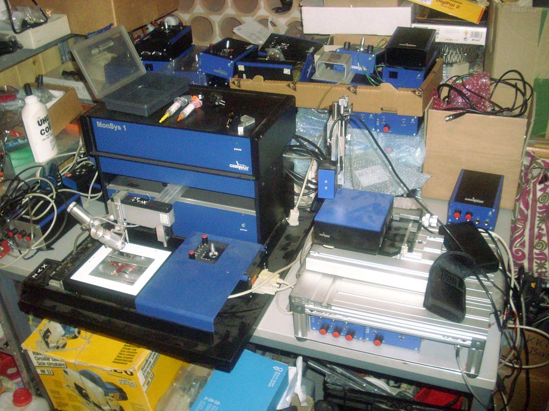
... i received some stuff from one of my previous employers who sold his company and 'disposes' all remains.
This were mostly the microassembly-tools i developed then - the modified manual SMD-placer mentioned in a previous post, a nanopositioner, some drivers and all the remaining microscope-cameras ... atached an image of the parts ...
Furthermore an image-recognition-system with a 1600x1200@40Hz BW-camera and a professional IR-Software, an old Leitz-tool-microscope, and different more ...
Now i have a big pile of tools and equipment for some SMD-pick-n-place or micro-/nanotech i can give away or sell for funding my other activities
If there is interest, PM me, then i can go more in detail ...
Viktor
--------
Aufruf zum Projekt "Müll-freie Meere" - [reprap.org] -- Deutsche Facebook-Gruppe - [www.facebook.com]
Call for the project "garbage-free seas" - [reprap.org]
|
Re: Pick and Place toolhead, STL files included! March 24, 2011 05:11PM |
Registered: 16 years ago Posts: 293 |
Because our pick-n-place partner was unreliable I renewed my interest in this subject. One of the baby steps I took was designing a tape feeder.
It would be useful as a manual aid for hand placement, and I would gradually work towards full automation. I've actually placed a few components with a GCode file and a vacuum membrane pump. The pump's flow, however, oscillates too much. I'm looking into the following options:
- venturi (aspirator): using an air pressure source and a T-junction, this seems to work.
- two mechanically coupled pistons, one that is driven by a flow, the other is pulled outward to create a vacuum (this is not continous, problematic)
- buffering the membrane pump somehow. Any ideas?
- some other off-the-shelf pump that doesn't oscillate? Or one with multiple pumping blades.
I'm also deciding on how to achieve accurate positioning. I guess I could use the SMT tape itself as a centering pit.
[www.ciciora.com]
Regards,
Erik de Bruijn
[Ultimaker.com] - [blog.erikdebruijn.nl]
|
Re: Pick and Place toolhead, STL files included! March 24, 2011 07:15PM |
Admin Registered: 17 years ago Posts: 7,879 |
I used an aquarium membrane pump to "pick and place" compact disks. Since it was mean't to blow and not suck I sealed the case and used the inlet as the vacuum. The case acted as a reservoir and I had no problem with oscillations. I used a homemade solenoid valve to turn it on and off sharply: [hydraraptor.blogspot.com]
I still have it and plan to use it for pick and place on my Darwin. For the centering pit I will print or mill an inverse stepped pyramid so small components can be centered just a fast as large ones by using a lower level.
[www.hydraraptor.blogspot.com]
I still have it and plan to use it for pick and place on my Darwin. For the centering pit I will print or mill an inverse stepped pyramid so small components can be centered just a fast as large ones by using a lower level.
[www.hydraraptor.blogspot.com]

Sorry, only registered users may post in this forum.