MINTEMP error with new silicone bed install, runaway heating
Posted by fullHundo
|
MINTEMP error with new silicone bed install, runaway heating April 12, 2017 01:48AM |
Registered: 7 years ago Posts: 40 |
Hi everyone!
I hope I chose the proper sub-forum for this issue. If not, please correct me. I have attached 3 images below to show my issue.
I have had my prusa i3 clone from RepRapGuru for a few weeks. I decided to install a new aluminum bed, silicone heat pad, and aluminum Y carriage from RepRap Champion (link) this past weekend. I also purchased and installed a MOSFET (link) to reduce the load on the RAMPS 1.4 board.
The problem I encountered was that while the thermistor wires on the silicone bed came pre-installed, they did not come with a 2-pin connector attached to them like the MK2 PCB heatbed that came with the printer kit. I had no way of connecting the thermistor to the RAMPS board short of soldering directly onto the T1 pins.
I went to RadioShack to see if I could buy the necessary hardware to install a connector myself, but they did not have much of anything in stock, especially not what I needed. So, I found a little electronics kit that had a wire of the same gauge (20 gauge) with a 2-pin connector pre-installed. It was exactly what I needed, just not yet connected to my thermistor wires. My reasoning was to solder this new wire onto my thermistor wires and use the connector to plug it into T1 on the RAMPS board.
So, I did that. As far as I could tell, the soldering went perfectly. I made sure that all wires had the same strand count of 7 strands each. I did not clip off any of the strands when stripping the wires. I took great care with the soldering, and made a very strong connection the proper way. I put shrink tubing over both solder points, then a larger shrink tube over all of it. It looked great all around to me. The attached photo named mintemp1.jpg shows this wire; it is the one with the blue shrink tube on it. I plugged this into T1 on RAMPS and turned on the printer, only to receive an immediate error code: MINTEMP. Worse than the error code, the silicone mat started heating up the moment it was plugged in and reached about 80 degrees before I noticed and unplugged the printer.
I will probably cut the wires again and re-attempt the soldering to rule out any issues there, but I'm at a loss beyond that. I tried inserting the connector both ways, although I am aware that polarity is not supposed to matter with this connection. That didn't help. After some research, it seems like the MINTEMP error code indicates that the silicone pad thermistor is not being detected, but I'm still new to all of this, so I don't know that for sure. The power wires for the silicone pad don't seem to have any polarity to them, but I tried connecting them to the MOSFET both ways to rule out that issue. It did not change anything.
Are there any changes that must be made to the firmware when switching from a PCB MK2 heater to a silicone pad? Also, I have a multimeter but I do not have experience in using it, so I do not know how to verify the thermistor wire voltages.
I feel like there are so many people who have made the switch to silicone heat pads, and I have yet to find anyone else struggling with the fact that the thermistor wires come without connectors. There must be something simple I am missing.
Any suggestions would be greatly appreciated, as I am stumped. If there are any videos or resources that specifically show this portion of the silicone pad installation, I have not been able to find them. But if you know of one, please share the link!
Thanks for taking your time to help.
|
Re: MINTEMP error with new silicone bed install, runaway heating April 12, 2017 02:33AM |
Registered: 8 years ago Posts: 5,232 |
Can you read the resistance of the unplugged thermistor with your multimeter? Should be in the range of 100kOhms.
If it is infinite, you have a dead thermistor. Usually they are sealed in the silicone bed, so you are screwed unless you find a different place to add a working thermistor. ( drill a hole in the center of the aluminum plate and place it there )
If it is infinite, you have a dead thermistor. Usually they are sealed in the silicone bed, so you are screwed unless you find a different place to add a working thermistor. ( drill a hole in the center of the aluminum plate and place it there )
|
Re: MINTEMP error with new silicone bed install, runaway heating April 12, 2017 03:51AM |
Registered: 7 years ago Posts: 40 |
I was unable to get a resistance reading with the connector attached, but I cut away the whole solder situation that I created and stripped some fresh wire from the heat pad thermistor wiring. Once I did that, I did get a reading right around 100kOhms. So that must mean my solder connection was the culprit? I know that this is basic stuff, but it was surprisingly hard to even find out what that connector was called to be able to order it, so I went with this solder fix. I guess it didn't work. I did some research and finally figured out what to call it: a 2.54mm 1x2P Dupont Connector. With that info, I was able to find the right hardware on amazon to do this right. Thank you for the help!
|
Re: MINTEMP error with new silicone bed install, runaway heating April 12, 2017 04:48AM |
Registered: 7 years ago Posts: 40 |
Well, it doesn't look like the solder point was the issue after all. I resoldered the connector wires to the thermistor wires and was able to get a 106kOhm reading through the connector this time. I powered up the printer again and still had the MINTEMP error code with automatic runaway bed heating. Next, I disconnected the heat bed setup entirely from the RAMPS and power supply, started the printer, and still got the MINTEMP error code (though of course the bed did not auto heat this time).
I just tested the resistance on the thermistor connector for the hot end, though, and I'm not getting a reading there. I did a lot of cable management over the weekend, so I may have damaged the hot end thermistor wiring. I don't want to mess with the hot end thermistor itself unless I have to though, because if I screw that up then I will have to wait a couple days for some new thermistors to arrive.
So, I'm wondering if the runaway heating and MINTEMP issues are entirely separate problems? Perhaps I have wired the heatbed to the power supply improperly? I just wired positive to the one unused positive terminal (terminal #1) on the power supply and negative to the one available negative terminal (terminal #6).
Here are my current questions:
1. When wiring the heated bed's MOSFET to the power supply, where am I supposed to connect the wires on the power supply itself? Do I use the only two available terminals (the first and sixth terminals on the power supply) Or am I supposed to be wiring it differently, like stacking onto terminals which are already in use?
2. Can I run the negative wire directly from the power supply to the MOSFET or do I need to wire it to some sort of ground before going to the MOSFET?
3. Are there any other potential causes for the MINTEMP error other than the thermistors for the hot end and heated bed?
Thanks, sorry for the torrent of information.
|
Re: MINTEMP error with new silicone bed install, runaway heating April 12, 2017 12:04PM |
Registered: 8 years ago Posts: 5,232 |
1) Doesn't matter where you put the cables. Just make sure they are all tight.
2) You have wired the Ramps power connector to the power supply and also the MOSFet. That means you already have common ground on the GND terminal of the Power supply. ( which is the best place for it )
3) It's always a good idea to inspect the hardware for soldered shortcuts, cold solder joints or loose solder blobs waiting for the right moment to cause hazard... The quality control is not the best in China...
The heated bed should not heat until you send the command to do so. Maybe you have to invert the Ramps output? What does the MOSFETs manual say?
Edited 1 time(s). Last edit at 04/12/2017 12:08PM by o_lampe.
|
Re: MINTEMP error with new silicone bed install, runaway heating April 12, 2017 01:23PM |
Registered: 7 years ago Posts: 40 |
Unfortunately, the MOSFET did not come with a single line of instructions. I actually followed the directions laid out by an Amazon reviewer on the product page. This is what he said to do:
1. Remove basically all ouside screws for your control box.
2. Take pictures of existing board wiring.
3. Unscrew two large 12/14GA wires on the board labeled "hot bed".
4. Screw these two wires into the new mosfet board labled "hot bed".
5. Connect the small jumper wires (white) to the control board where you just removed the two wires and screw them down. Note the polarity on each board. Match (+) to (+) and (-) to (-).
6. Find 2x 6-8" pieces of 12 or 14 AWG wire.
7. Run one of the 6" wires to the power supply (+), screw in; and the other side to the (+) DC IN on the new mosfet board. Repeat for the negative wire (-) to (-).
8. Many people use velcro to secure the new board to the top of the control box. Others print off a holder from thingiverse.
9. Put everything back together.
10. When complete, you'll see a blue light activate for signal from inside the box when the bed heater is activated by the control board.
I will try reversing the polarity going from RAMPS to the MOSFET to see if that fixes the heating issue.
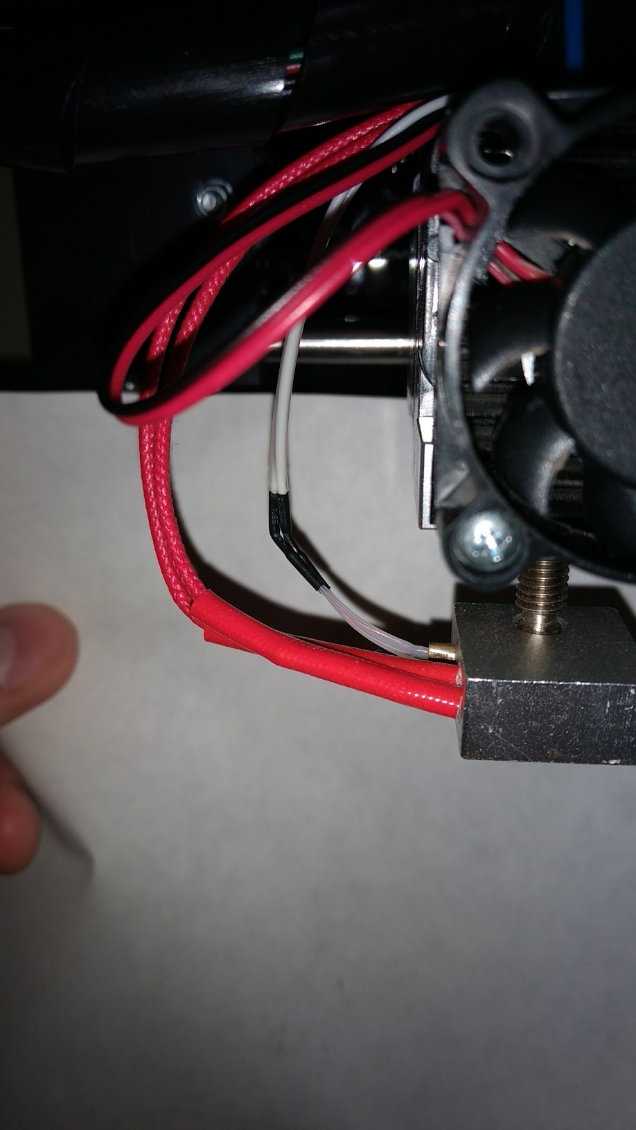
I have attached a photo of what I think may be the MINTEMP error culprit. There is a noticeable kink at the point where the thermistor is attached to its wiring. Does this appear to be a possible point of failure to you?
Thanks again.
1. Remove basically all ouside screws for your control box.
2. Take pictures of existing board wiring.
3. Unscrew two large 12/14GA wires on the board labeled "hot bed".
4. Screw these two wires into the new mosfet board labled "hot bed".
5. Connect the small jumper wires (white) to the control board where you just removed the two wires and screw them down. Note the polarity on each board. Match (+) to (+) and (-) to (-).
6. Find 2x 6-8" pieces of 12 or 14 AWG wire.
7. Run one of the 6" wires to the power supply (+), screw in; and the other side to the (+) DC IN on the new mosfet board. Repeat for the negative wire (-) to (-).
8. Many people use velcro to secure the new board to the top of the control box. Others print off a holder from thingiverse.
9. Put everything back together.
10. When complete, you'll see a blue light activate for signal from inside the box when the bed heater is activated by the control board.
I will try reversing the polarity going from RAMPS to the MOSFET to see if that fixes the heating issue.
I have attached a photo of what I think may be the MINTEMP error culprit. There is a noticeable kink at the point where the thermistor is attached to its wiring. Does this appear to be a possible point of failure to you?
Thanks again.
|
Re: MINTEMP error with new silicone bed install, runaway heating April 13, 2017 03:07AM |
Registered: 8 years ago Posts: 5,232 |
Quote
I will try reversing the polarity going from RAMPS to the MOSFET to see if that fixes the heating issue.
STOP!
Don't reverse the wires between Ramps and Mosfet. ( It doesn't hurt to check if they were the wrong way round )
I wrote " Invert the signal", which means you have to look in firmware for such an option. But I'm afraid that won't help.
A MINtemp error on the extruder has nothing to do with a permanently heating bed. Or did I get you wrong about which thermistor reads 100k and which doesn't?
|
Re: MINTEMP error with new silicone bed install, runaway heating April 13, 2017 02:28PM |
Registered: 7 years ago Posts: 41 |
I think o_lampe is correct, and you are dealing with two separate issues here. You have your bed thermistor connected to T1, and the LCD shows the controller is reading a bed temp of 20C, so it looks like that is correct. You have a min temp error, and your LCD shows the hot end has a temp is 0C, which is where your problem is. So something isn't right with your hot end thermistor, it appears your bed thermistor is working fine.
As for your mosfet, it sounds like you wired it up correctly. If you have a volt meter, I would check the voltage on the bed connectors on the controller. If there is no voltage there, it is possible the mosfet is defective and stuck closed.
As for your mosfet, it sounds like you wired it up correctly. If you have a volt meter, I would check the voltage on the bed connectors on the controller. If there is no voltage there, it is possible the mosfet is defective and stuck closed.
|
Re: MINTEMP error with new silicone bed install, runaway heating April 20, 2017 04:01AM |
Registered: 7 years ago Posts: 40 |
Thank you for all the help, o_lampe. I misunderstood when you said to invert the signal, but I also checked the specs on my heated mat before making any changes and the manufacturer said there is no polarity for this particular silicone mat's wiring. Regardless, reversing the wires had no effect anyway. Thanks for the input as well, Pheneeny. I was able to solve both problems once I bought a nice set of automatic wire strippers, a good crimping tool, and connectors.
The heated bed problem was fixed once I crimped a nice, permanent connector onto the heated bed thermistor wires directly. The mintemp error was, in fact, a result of the faulty solder connection between the hot end thermistor and its wiring. I re-soldered these connections and reinforced them with an additional shrink tube to relieve strain, and all problems were solved.
I'm now hitting a few new issues, though, and I'm really starting to get discouraged. Once I solved the above problems, I did some test prints and they turned out beautifully. Then, I decided to change filament, but apparently I did it incorrectly and caused a clog in the hot end. I tried to remove the hot end, but I did so while it was at room temp and wound up applying too much torque and broke off the threaded portion of the nozzle in the heater block. I waited a few days for new nozzles to arrive, installed one, leveled the bed and nozzle height, and did a test print. It was under extruding horribly. About half of my first and second layers were extruding nice and dense, and then it would begin barely extruding for a few lines before beginning to extrude acceptably again. I followed Tom Sanladerer's extruder calibration video, but for the life of me I can't get the extruder motor properly calibrated. No matter how high or low the calculations tell me to set the steps/mm (I've tried many values between 96 and 126 steps/mm) it keeps under extruding. I adjusted the extrusion multiplier in my slicing software up to 1.2x, then 1.6x, and I still had under extrusion problems in areas. I used all the same slicing settings that had worked great before. I had no idea where to turn next, so I decided to see about adjusting the voltage on my stepper drivers.
This is where I caused my most immediate problem. All of my stepper motor drivers were set to 0.55 V. After a lot of research, I figured I could safely change it to 0.60. I wasn't careful enough, and while testing the voltage of the extruder stepper motor with my meter, I think I may have shorted something out as I saw a small spark of electricity when my grounding probe slipped off of the pin I held it to. I then carefully checked the voltage on all of the stepper motor drivers and found they were all now reading around 0.6 V. I thought that was strange, because I hadn't adjusted any of them from 0.55, but the printer was still powered on and didn't seem to be malfunctioning. So, I attempted to print a calibration cube. It printed the first layer (still under-extruding), but then I noticed that the LCD screen was dimmer than usual. I killed the print and unplugged the USB cable from the computer. The LCD screen shut off even though it should stay on, as the power supply was still plugged into wall power. It seems as though I must have fried something, but I have no idea what to check. I gave it some time, plugged the printer back into wall power, but still showed no sign of power to components. Leaving it plugged in, I connected the USB cable to the computer. The screen came on, but at half brightness. The lights came on for the triggered end stops. Through repetier, I was able to manually control the stepper motors and move along the axes. I was even able to heat the bed and extruder by a few degrees (albeit slowly). When I attempted heating, the power supply fan whirred up like normal as though it were working properly, but the moment I disconnected the USB from the computer, the printer died again.
So, my self-inflicted problems are just snowballing. I need to figure out this power issue first. Any suggestions on what could be the root of this half-failure? Did I short the power supply, the ramps board, arduino board, or a motor driver? Why would I be able to control the unit through the computer as long as the power was still plugged into the wall, but not able to do anything without the USB power from the computer? Aargh, I'm really learning the virtue of patience the hard way.
|
Re: MINTEMP error with new silicone bed install, runaway heating April 21, 2017 03:04AM |
Registered: 8 years ago Posts: 5,232 |
The shortcut killed the 5V regulator on the controller. That's why it only works with 5V supplied by USB.
A quick cure is to use an active USB hub with it's own powersupply, so you don't have to be connected to a PC all the time.
In the long run you need to replace the controller ( Arduino Mega? )
A quick cure is to use an active USB hub with it's own powersupply, so you don't have to be connected to a PC all the time.
In the long run you need to replace the controller ( Arduino Mega? )
|
Re: MINTEMP error with new silicone bed install, runaway heating April 25, 2017 04:02AM |
Registered: 7 years ago Posts: 40 |
Okay, that makes sense. Thank you for the USB hub tip, that's a great idea. Yes, I have been using an Arduino Mega/RAMPS 1.4 combo. Is the blown regulator on the RAMPS board or the Arduino itself? I decided to upgrade to a BIQU MKS Base v1.5 board, which has an onboard Atmega 2560 chip. It replaces both of those boards, but I will eventually build another printer with the original parts that are still operational.
The RAMPS board has two 12v power inputs from the PSU, but this new board only has one power input (diagram attached). I assume this is on purpose, but I am wondering about the difference. Does this affect performance? Is the second set of power inputs not necessary, or does this put the machine at any risk? I imagine it is fine, but I'm not interested in messing up anymore so I'd rather sound silly asking. Thanks!
The RAMPS board has two 12v power inputs from the PSU, but this new board only has one power input (diagram attached). I assume this is on purpose, but I am wondering about the difference. Does this affect performance? Is the second set of power inputs not necessary, or does this put the machine at any risk? I imagine it is fine, but I'm not interested in messing up anymore so I'd rather sound silly asking. Thanks!
Sorry, only registered users may post in this forum.