Type-K Thermocouple - Affects of shortening leads.
Posted by elgin.owens
|
Type-K Thermocouple - Affects of shortening leads. January 30, 2011 09:11PM |
Registered: 13 years ago Posts: 16 |
I've googled and searched the forums for answers on this to no avail, so if anyone could help me out here it would be greatly appreciated.
I purchased a thermocouple kit off ebay which came with the v1.0 board and a Type-K thermocouple. I'd like to mount my thermocouple sensor v1.0 board to the bottom of the extruder. Having the board mounted to the extruder means that the leads that came on my Type-K thermocouple are way to long, so I would like to cut them shorter. The thermocouple has a length of 90cm and a yellow connector on it. I will obviously need to cut off the connector, in order to connect it to the screw terminals on the sensor board.
My question is, how much length can I cut off the thermocouple leads without affecting the accuracy of it. I'd like to shorten the leads on the thermocouple to be around 20cm, but I understand that the thermocouple's temperature measurements are dependent on resistance and as such could be affected by changing the length of the leads.
What's your take on this? If you have cut the connector off your thermocouple or shortened the overall length of it did you noticed any affect on the accuracy of it?
|
Re: Type-K Thermocouple - Affects of shortening leads. January 30, 2011 09:56PM |
Registered: 13 years ago Posts: 643 |
|
Re: Type-K Thermocouple - Affects of shortening leads. January 30, 2011 10:06PM |
Registered: 13 years ago Posts: 16 |
|
Re: Type-K Thermocouple - Affects of shortening leads. January 30, 2011 10:41PM |
Registered: 13 years ago Posts: 16 |
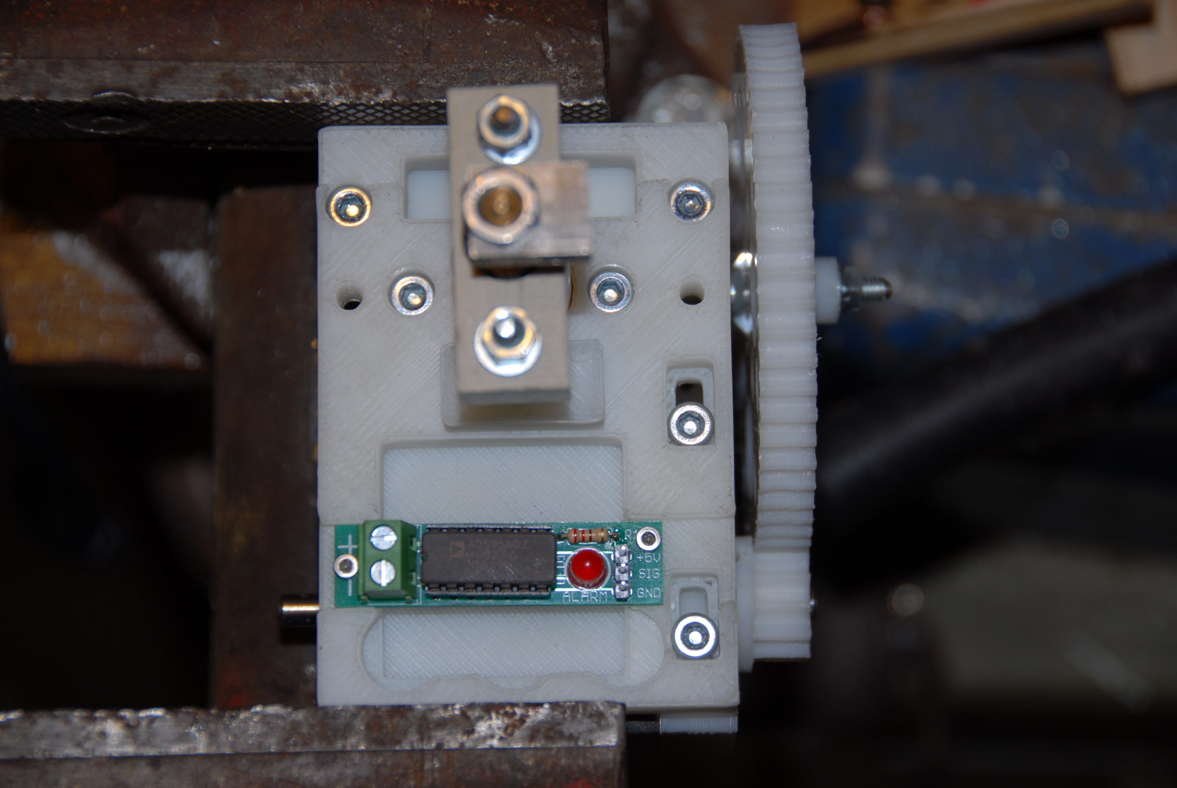
Ok, dinner is over and I'm back to share my picture. The picture is showing how I mounted the Thermocouple Sensor Board V1.0 to the bottom of Adrian's Geared Extruder. I haven't seen anything on where other people are mounting their boards, so I thought I would share what I came up with. It is held on with two 2mm screws, which I have tapped and drilled holes for. Enjoy!
|
Re: Type-K Thermocouple - Affects of shortening leads. January 31, 2011 12:11AM |
Registered: 14 years ago Posts: 1,092 |
|
Re: Type-K Thermocouple - Affects of shortening leads. January 31, 2011 12:48AM |
Registered: 13 years ago Posts: 16 |
Cefiar: Since your asking I'm guessing that it will not fit once mounted to the X-carriage.
To be entirely honest, I didn't even look at how the extruder is attached to the X-Carriage so I really have no idea. It just seamed like a really sweet spot to mount it with the perfect sized groove already there and what not. Thank god you said something, otherwise I would have cut my thermocouple really short!
Edit: Ok, I looked at the X-Carriage mounting issue and it is definitely a no go. Oops looks like I'm gonna have to find somewhere else to mount that tomorrow. I'll keep you posted.
Edited 1 time(s). Last edit at 01/31/2011 01:06AM by elgin.owens.
|
Re: Type-K Thermocouple - Affects of shortening leads. January 31, 2011 05:49AM |
Registered: 13 years ago Posts: 1,352 |
I personally avoided mounting it near the extruder, as typically i dont trust datasheets haha, so i went for the alternative, which i believe is to extend the thermocouple wires by means of simple copper wires (copper should be used for this i think). I mounted the board along with the other electronics alltogether, still fairly close, and having the thermocouple wires cutted down to like 10 cm, i extended them with normal (copper!) wires over the area that needs to be flexible for the carriage movement.
Also did quite some hacking because the readings were not quite stable as i wanted them. First chopped the board into like 3 variants, used compensation caps on pins 9-10-11 (may be beneficial if running the wires together along with extruder stepper ones), plus an rc filter, but i saw none or minimal improvement. As the noise picked by thermocouple can be excluded when the outputs are shorted to each other (it reads room temp), then rc filter + 5v linear reg suplly can exclude supply noise, the signal wire back being shielded, i figured there must be something with the internal chip adc. It seems it cant take readings of two analog pins without getting some internal noise on the adc. The issue is presented like minimal, but i think its more to it than what is being said. Thus, readings need to be done at max timing interval possible. Also the adc on EC 2.2v has Aref to 5v but at the same time the default is to use internal 5v, and no firmware that i seen for EC2.2 had analogReference(EXTERNAL) (to use aref 5v). Which means the adc gets 2 supply of 5v and thus could get turbinoary effects and at some extent could get anything from some extra noise to getting damaged if wrong settings are used. Also tested having an average of the analogread sampling and effect seems none or minimal, will have to test increasing the clock next week.
At this point i guess that the alternative, max6675 chip seems to be better because it uses its own adc, leaving the atmel adc to make a single reading (the heated bed, or anyway, the "other" reading), thus having much less noise caused because of the internal adc multiple readings issue.
That being said, at start it had an occasional (like each 5-6-7 seconds) sudden drop of like 5-6 degrees from the last reading to the next one, and then back. Plus each constant fluctuations readings of either + or - one degree. All this at room temp, at higher temp seems more stable (no clue why or how it affects adc or what it does affect if not adc is the issue). With all stuff done, cant exactly pinpoint the cause since i did more changes each step, but the big drop seems to be gone, while the small fluctuations of 1 degree +/- are still there, just a little more stable if it can be said so - or i just got bored enough to see it that way.
I will be curious if you can share these kind of results with me once you get it working.
Cheers and good luck.
|
Re: Type-K Thermocouple - Affects of shortening leads. January 31, 2011 06:14AM |
Admin Registered: 17 years ago Posts: 7,879 |
You can't extend the wires with copper without affecting the results. You need to extend them with same metal as they are made of otherwise you create more thermocouples at different temperatures in series. That is what those funny yellow plugs with different metals on each pin are all about.
A thermocouple has a hot and a cold junction and the voltage is proportional to the difference between the two. The cold junction is at the connection to the PCB and the chip has a temperature sensor built in so that it knows the temperature of the cold junction, assuming it is nearby on the PCB.
To get stable readings you need to be careful with the ground connections and filter the 5V. Have a look at the hack I did here: [hydraraptor.blogspot.com]. The ground path between the thermocouple PCB and the analogue ground of the ADC must not be shared with anything drawing significant current.
[www.hydraraptor.blogspot.com]
|
Re: Type-K Thermocouple - Affects of shortening leads. January 31, 2011 09:10AM |
Registered: 13 years ago Posts: 1,352 |
Oh sir, i have read your page at least 5 times top to bottm 
And datasheet and application notes AN274 and AN369 plus some datasheet and app notes of further analogdevices ics including the new one supposed to replace the 595, there are a few more ideeas about filtering the thermocouple wires noise, rc filter on it, 3-capacitors filter on them, etc, i passed to all that anyway, but i did some homework at least.
For tests i shortened the thermocouple outputs (so these caps dont make a difference i think) but for board i made one with both compensation caps on pins 9-10-11 and another board with just one (my values 100nf and 470pf). That because i wired all together with stepper wires, in the "elastic" area - just with separate shieldings. Originally i used a board without any comp caps.
It gets 5v from the 5v linear v reg on ec2.2, plus using rc filter on supply input (like in your page or also in app notes) values i settled for being 1k resistor with 10uf electrolitic cap. As it said to draw like 160microamps, i guess the resistor could be way higher. On the other hand just 5v i thought 10uf cap should be ok. Tried rated one 6.3v but went for using some rated 25v ones, metered to give stable readings.
Because for testing i short the thermocouple outputs to themselives / bridging one to another, the ad595 runs without any thermocouple wiring attached, so it just reads the room temperature as a stand alone thermometer. I think it can do that up to 125C. Extending the wires with copper ideea i got from application notes. I agree that the wires added can make a difference, but for the test setup they arent used. Indeed it works like another series thermocouple, it gives like an extra ~10 degrees reading or so comparing the setup of with it and without it. I would settle with that as a sort of offset, if the chip itself would give stable readings.
That being said, i hit the wall with the ad595 board, couldnt figure what else should i change except maybe changing the wiring, e.g. having 5v on one wire shielded and signal to another wire shielded separatelly.
So i went to take a look at mcu datasheet and notes, and its said that if the adc makes two analogRead() of two different pins, these readings should be as much different apart in time as possible. So i changed the count value for the bed reading to be at half interval, e.g. trying to make one reading at half of the setted clock and the other when its full, sort of like in anti-phase.
Also i noticed that on normal extruder controller 2.2, the Aref is tied to 5v line, although this doesnt seem to appear in schematic, only on board layout (noticed this also first when i built it). However, in spite of having the Aref to 5v, the default reference for adc is the internal 5v, which it gets from the other side of the board/chip. My intepretation is that if multiple gnds can make turbionary stuff inside ics, maybe 5v can do the same, so i have cutted off the Aref from the 5v line (kept the decoupling cap c14 to gnd tho), and putted a jumper. This way i tried both with internal adc 5v (default) without anything on Aref and also i tried with analogReference(EXTERNAL) and Aref to 5v. Cant say i noticed any difference again.
In the end i changed everything, slow_clock huge values, bedcount with half start advance, let the aref disconnected from 5v but to gnd with decoupling cap, and used default internal 5v. Also tried to make multiple analog readings 2-3, take average and use average to compute the result volts-celsius.
I still get something like 3 equal values, next one -1C, and again like more or less constant fluctuations with +/- 1 degree, and very rarelly i get 5-6 consecutive reading of the same value.
I used 3 boards, with the initial one, and 3 ad595 ics, and tempered with my firmware as much as i could figure. Dunno what to do next. I am convinced there is something that i am missing, just cant figure it. I am going to take a break and get to it next week with a fresh pov. If i get lucky, with my friend's scope too.
Btw, i started messing up the firmware because i noticed, on pins A7 and A6, which are free floating, if i define 7 to read thermocouple, i get voltage ~2volts on the other one.
Also at a point, it was funny, i defined both 6 and 7 (normally i have either +3 for thermistor), and having only one board connected to 7, the mcu outputs himself a voltage on 6, and then reads it and reports it as value. Again, there is nothing connected, free floating pin, but it reports, intepreting the reading of the voltage it outputs himself. Funny. No clue if its supposed to be like that or not. Maybe i blew something up. Auch. Less funny. I wont be able to check-in for a few days, but i will be looking forward to get any tips for this matter.
My guess is that the board for ad595 is ok, but my adc at least, has some trouble making two separate analog reads, or there is something i am missing about it. Will see next week, and as soon as i figure it all out, i will make the appropriate section on my diy toner transfer page with the firmware included to get proper 2 readings and bed control in. Just too confused about it all atm.
And datasheet and application notes AN274 and AN369 plus some datasheet and app notes of further analogdevices ics including the new one supposed to replace the 595, there are a few more ideeas about filtering the thermocouple wires noise, rc filter on it, 3-capacitors filter on them, etc, i passed to all that anyway, but i did some homework at least.
For tests i shortened the thermocouple outputs (so these caps dont make a difference i think) but for board i made one with both compensation caps on pins 9-10-11 and another board with just one (my values 100nf and 470pf). That because i wired all together with stepper wires, in the "elastic" area - just with separate shieldings. Originally i used a board without any comp caps.
It gets 5v from the 5v linear v reg on ec2.2, plus using rc filter on supply input (like in your page or also in app notes) values i settled for being 1k resistor with 10uf electrolitic cap. As it said to draw like 160microamps, i guess the resistor could be way higher. On the other hand just 5v i thought 10uf cap should be ok. Tried rated one 6.3v but went for using some rated 25v ones, metered to give stable readings.
Because for testing i short the thermocouple outputs to themselives / bridging one to another, the ad595 runs without any thermocouple wiring attached, so it just reads the room temperature as a stand alone thermometer. I think it can do that up to 125C. Extending the wires with copper ideea i got from application notes. I agree that the wires added can make a difference, but for the test setup they arent used. Indeed it works like another series thermocouple, it gives like an extra ~10 degrees reading or so comparing the setup of with it and without it. I would settle with that as a sort of offset, if the chip itself would give stable readings.
That being said, i hit the wall with the ad595 board, couldnt figure what else should i change except maybe changing the wiring, e.g. having 5v on one wire shielded and signal to another wire shielded separatelly.
So i went to take a look at mcu datasheet and notes, and its said that if the adc makes two analogRead() of two different pins, these readings should be as much different apart in time as possible. So i changed the count value for the bed reading to be at half interval, e.g. trying to make one reading at half of the setted clock and the other when its full, sort of like in anti-phase.
Also i noticed that on normal extruder controller 2.2, the Aref is tied to 5v line, although this doesnt seem to appear in schematic, only on board layout (noticed this also first when i built it). However, in spite of having the Aref to 5v, the default reference for adc is the internal 5v, which it gets from the other side of the board/chip. My intepretation is that if multiple gnds can make turbionary stuff inside ics, maybe 5v can do the same, so i have cutted off the Aref from the 5v line (kept the decoupling cap c14 to gnd tho), and putted a jumper. This way i tried both with internal adc 5v (default) without anything on Aref and also i tried with analogReference(EXTERNAL) and Aref to 5v. Cant say i noticed any difference again.
In the end i changed everything, slow_clock huge values, bedcount with half start advance, let the aref disconnected from 5v but to gnd with decoupling cap, and used default internal 5v. Also tried to make multiple analog readings 2-3, take average and use average to compute the result volts-celsius.
I still get something like 3 equal values, next one -1C, and again like more or less constant fluctuations with +/- 1 degree, and very rarelly i get 5-6 consecutive reading of the same value.
I used 3 boards, with the initial one, and 3 ad595 ics, and tempered with my firmware as much as i could figure. Dunno what to do next. I am convinced there is something that i am missing, just cant figure it. I am going to take a break and get to it next week with a fresh pov. If i get lucky, with my friend's scope too.
Btw, i started messing up the firmware because i noticed, on pins A7 and A6, which are free floating, if i define 7 to read thermocouple, i get voltage ~2volts on the other one.
Also at a point, it was funny, i defined both 6 and 7 (normally i have either +3 for thermistor), and having only one board connected to 7, the mcu outputs himself a voltage on 6, and then reads it and reports it as value. Again, there is nothing connected, free floating pin, but it reports, intepreting the reading of the voltage it outputs himself. Funny. No clue if its supposed to be like that or not. Maybe i blew something up. Auch. Less funny.
I wont be able to check-in for a few days, but i will be looking forward to get any tips for this matter. My guess is that the board for ad595 is ok, but my adc at least, has some trouble making two separate analog reads, or there is something i am missing about it. Will see next week, and as soon as i figure it all out, i will make the appropriate section on my diy toner transfer page with the firmware included to get proper 2 readings and bed control in. Just too confused about it all atm.
|
Re: Type-K Thermocouple - Affects of shortening leads. January 31, 2011 09:33AM |
Registered: 13 years ago Posts: 1,352 |
My stupidly retarded firmare with only the thermocouple - e.g. one analogRead to do, as standalone themometer (short outputs) :
=========================================
Native lib Version = RXTX-2.1-7
Java lib Version = RXTX-2.1-7
comms: G-code: N0 M110 *3 dequeued and sent [0.000s/-1296483042859ms]
comms: Response: ok [0.000s/0ms]
comms: G-code: N1 T0 *27 dequeued and sent [2.719s/2719ms]
comms: Response: ok [2.734s/15ms]
comms: G-code: N2 M113 *2 dequeued and sent [2.734s/0ms]
comms: Response: ok ED [2.750s/16ms]
comms: G-code: N3 M105 *4 dequeued and sent [2.766s/16ms]
comms: Response: ok T:23 B:0 [2.781s/15ms]
comms: Response: ok T:23 B:0 [4.297s/0ms]
comms: Response: ok T:23 B:0 [5.828s/16ms]
comms: Response: ok T:23 B:0 [5.859s/31ms]
comms: Response: ok T:23 B:0 [7.375s/16ms]
comms: Response: ok T:23 B:0 [8.891s/16ms]
comms: Response: ok T:23 B:0 [10.406s/0ms]
comms: Response: ok T:23 B:0 [10.453s/31ms]
comms: Response: ok T:23 B:0 [11.969s/16ms]
comms: Response: ok T:23 B:0 [13.484s/15ms]
comms: Response: ok T:23 B:0 [15.000s/16ms]
comms: Response: ok T:23 B:0 [15.031s/15ms]
With thermistor alone, the readings are ofc same accurate.
The same firmware, but more stupid, more retarded, behaving like it got aids: i.e. with two analogReads, e.g. thermocouple (standalone with short outputs) and thermistor pin 3:
=========================================
Native lib Version = RXTX-2.1-7
Java lib Version = RXTX-2.1-7
comms: G-code: N0 M110 *3 dequeued and sent [0.016s/-1296483377593ms]
comms: Response: ok [0.016s/0ms]
comms: G-code: N1 T0 *27 dequeued and sent [2.719s/2703ms]
comms: Response: ok [2.734s/15ms]
comms: G-code: N2 M113 *2 dequeued and sent [2.734s/0ms]
comms: Response: ok ED [2.750s/16ms]
comms: G-code: N3 M105 *4 dequeued and sent [2.750s/0ms]
comms: Response: ok T:24 B:22 [2.781s/31ms]
comms: Response: ok T:19 B:22 [4.297s/16ms]
comms: Response: ok T:23 B:22 [5.812s/15ms]
comms: Response: ok T:18 B:22 [5.844s/16ms]
comms: Response: ok T:24 B:22 [7.375s/16ms]
comms: Response: ok T:18 B:22 [8.906s/31ms]
comms: Response: ok T:21 B:22 [10.422s/16ms]
comms: Response: ok T:20 B:22 [10.453s/16ms]
comms: Response: ok T:23 B:22 [11.969s/16ms]
comms: Response: ok T:24 B:22 [13.500s/16ms]
comms: Response: ok T:24 B:22 [15.016s/16ms]
comms: Response: ok T:18 B:22 [15.047s/31ms]
comms: Response: ok T:20 B:22 [16.578s/31ms]
comms: Response: ok T:23 B:22 [18.109s/15ms]
comms: Response: ok T:23 B:22 [19.641s/16ms]
comms: Response: ok T:20 B:22 [19.672s/31ms]
comms: Response: ok T:23 B:22 [21.187s/15ms]
Note: with all the tweaks and changes, the T fluctuations (the ad595) can get them narrow to +/- 1 degree. But still i cant call that stable. Over-bypassing this would be to make the control to read a dead zone of the target temp, start with smth like 2 degrees lower and shut at 2 degrees higher, but i would like to solve the problem instead of putting it under the carpet.
The firmware is hard rip of official firmware, e.g. - a3949 hack, -paste extruder, -pid (simple bang-bang), plus i invented some new function and stuff that i have no exact clue what it does. Sorry if it looks like crap, i have never took any programming lessons, not even electronics for that matter (my degrees are good to be put on the pickle jar, e,g, one in marketing and one in management). This is just what i came up with in like a week because the official firmware started to give names to thermistors, the pulley no of teeths, and i guess soon the color of your mendel and my sex and age and marital status will have to go in there, so i just wanted something plain and simple of what i can figure out clear, sort of to feel more in touch with the stuff.
I plan to further tweak increasing slow_clock, using the analog reads in antiphase (max time between them - does it work like that?) maybe using 2-3-4 samples for ad595 reaging, making proper definition of adc Aref to either external or default, and to corespond on the board layout, but cant figure out what else.
Any help with pointing to something that is wrong in firmware will be greatly appreciated.
I only tweaked extruder.h extruder_class, and ofc the configuration.h, havent touched the intercom and the other stuff.
Edited 2 time(s). Last edit at 02/14/2011 11:03AM by NoobMan.
=========================================
Native lib Version = RXTX-2.1-7
Java lib Version = RXTX-2.1-7
comms: G-code: N0 M110 *3 dequeued and sent [0.000s/-1296483042859ms]
comms: Response: ok [0.000s/0ms]
comms: G-code: N1 T0 *27 dequeued and sent [2.719s/2719ms]
comms: Response: ok [2.734s/15ms]
comms: G-code: N2 M113 *2 dequeued and sent [2.734s/0ms]
comms: Response: ok ED [2.750s/16ms]
comms: G-code: N3 M105 *4 dequeued and sent [2.766s/16ms]
comms: Response: ok T:23 B:0 [2.781s/15ms]
comms: Response: ok T:23 B:0 [4.297s/0ms]
comms: Response: ok T:23 B:0 [5.828s/16ms]
comms: Response: ok T:23 B:0 [5.859s/31ms]
comms: Response: ok T:23 B:0 [7.375s/16ms]
comms: Response: ok T:23 B:0 [8.891s/16ms]
comms: Response: ok T:23 B:0 [10.406s/0ms]
comms: Response: ok T:23 B:0 [10.453s/31ms]
comms: Response: ok T:23 B:0 [11.969s/16ms]
comms: Response: ok T:23 B:0 [13.484s/15ms]
comms: Response: ok T:23 B:0 [15.000s/16ms]
comms: Response: ok T:23 B:0 [15.031s/15ms]
With thermistor alone, the readings are ofc same accurate.
The same firmware, but more stupid, more retarded, behaving like it got aids: i.e. with two analogReads, e.g. thermocouple (standalone with short outputs) and thermistor pin 3:
=========================================
Native lib Version = RXTX-2.1-7
Java lib Version = RXTX-2.1-7
comms: G-code: N0 M110 *3 dequeued and sent [0.016s/-1296483377593ms]
comms: Response: ok [0.016s/0ms]
comms: G-code: N1 T0 *27 dequeued and sent [2.719s/2703ms]
comms: Response: ok [2.734s/15ms]
comms: G-code: N2 M113 *2 dequeued and sent [2.734s/0ms]
comms: Response: ok ED [2.750s/16ms]
comms: G-code: N3 M105 *4 dequeued and sent [2.750s/0ms]
comms: Response: ok T:24 B:22 [2.781s/31ms]
comms: Response: ok T:19 B:22 [4.297s/16ms]
comms: Response: ok T:23 B:22 [5.812s/15ms]
comms: Response: ok T:18 B:22 [5.844s/16ms]
comms: Response: ok T:24 B:22 [7.375s/16ms]
comms: Response: ok T:18 B:22 [8.906s/31ms]
comms: Response: ok T:21 B:22 [10.422s/16ms]
comms: Response: ok T:20 B:22 [10.453s/16ms]
comms: Response: ok T:23 B:22 [11.969s/16ms]
comms: Response: ok T:24 B:22 [13.500s/16ms]
comms: Response: ok T:24 B:22 [15.016s/16ms]
comms: Response: ok T:18 B:22 [15.047s/31ms]
comms: Response: ok T:20 B:22 [16.578s/31ms]
comms: Response: ok T:23 B:22 [18.109s/15ms]
comms: Response: ok T:23 B:22 [19.641s/16ms]
comms: Response: ok T:20 B:22 [19.672s/31ms]
comms: Response: ok T:23 B:22 [21.187s/15ms]
Note: with all the tweaks and changes, the T fluctuations (the ad595) can get them narrow to +/- 1 degree. But still i cant call that stable. Over-bypassing this would be to make the control to read a dead zone of the target temp, start with smth like 2 degrees lower and shut at 2 degrees higher, but i would like to solve the problem instead of putting it under the carpet.
The firmware is hard rip of official firmware, e.g. - a3949 hack, -paste extruder, -pid (simple bang-bang), plus i invented some new function and stuff that i have no exact clue what it does. Sorry if it looks like crap, i have never took any programming lessons, not even electronics for that matter (my degrees are good to be put on the pickle jar, e,g, one in marketing and one in management). This is just what i came up with in like a week because the official firmware started to give names to thermistors, the pulley no of teeths, and i guess soon the color of your mendel and my sex and age and marital status will have to go in there, so i just wanted something plain and simple of what i can figure out clear, sort of to feel more in touch with the stuff.
I plan to further tweak increasing slow_clock, using the analog reads in antiphase (max time between them - does it work like that?) maybe using 2-3-4 samples for ad595 reaging, making proper definition of adc Aref to either external or default, and to corespond on the board layout, but cant figure out what else.
Any help with pointing to something that is wrong in firmware will be greatly appreciated.
I only tweaked extruder.h extruder_class, and ofc the configuration.h, havent touched the intercom and the other stuff.
Edited 2 time(s). Last edit at 02/14/2011 11:03AM by NoobMan.
|
Re: Type-K Thermocouple - Affects of shortening leads. January 31, 2011 01:13PM |
Registered: 13 years ago Posts: 16 |
Reading all the struggles that NoobMan has had with his thermocouple setup is not encouraging. But then again, I didn't understand most of what he said.
nophead: Good advice, as always. I've got a couple questions after reading all this.
1. What is the ADC or more specifically what is the "analogue ground of the ADC", that you refer to? Is that on the extruder board somewhere?
2. Would you recommend that I use a RC filter consisting of a 1K series resistor and a 22uF capacitor?
I understand from what I've read so far, that the thermocouple board is not going to go to the two screw terminals, which would normally be used for the thermistor, but instead go to A6 or A7, is that correct? Then for my heated bed I plan to use a thermistor, would I use the thermistor inputs on the extruder board and then define that somewhere in the firmware?
Edited 1 time(s). Last edit at 01/31/2011 01:54PM by elgin.owens.
|
Re: Type-K Thermocouple - Affects of shortening leads. January 31, 2011 02:21PM |
Registered: 13 years ago Posts: 1,352 |
I hope my struggle is temporarily as i hope to get to an end with it, as usually its said "the smart one gives up", so all i have to do i to be stuborn and stupid enough to overcome it, which is kinda my specialty Now seriously, I lack the inteligence and education so i have to put more work and more muscle and time to compensate. And tbh, i dont understand what i was writing either, i mix up things as i usually do.
Was trying to say that ad595 is ok for single read, but i find it not really stable in having a dual sensors with one being ad595. Anyway, all the stuff is done by me (= at least 10 things are wrong), and the firmware is a pile of ... uhhh (coz i messed with it ofc, coz i couldnt find one to both work for this and also understand it). The normal firmware doesnt even compile not to mention working both Extruder and Bed. This stuff i adapted at least works, but its not stable as i would like it to be.
The little point i want to see at horizon is to to have it compatible with skeinforge or other programs for heated bed management even if using a relay instead of like 7 amps on that little board. As it looks now, in the worst case, i may not do it with ad595, but with maybe 2 thermistors or maybe with a max6675 - which i dont have so that code part was not rly tested. I think that normally thermistors and max6675 may be better because of the way they work, system results would be more stable at least. So, if i dont overcome this wall i am hitting with ad595, i am going to go around it.
I am not yet at conclusion stage, and would like to see if some1 with and EC 2.2v board and a ad595 can upload that stuff and tell me if the results are the same in comparison. That is, before i start to assume its something wrong with my own chip and starting to hack it off to put another in. Or actually i would start chopping out anything that is on all A0-A7 pins, first to be that 10k pot which i suspect inputs like 2v into the adc which i am seeing on another pins that are not even used.
Now seriously, I lack the inteligence and education so i have to put more work and more muscle and time to compensate. And tbh, i dont understand what i was writing either, i mix up things as i usually do. Was trying to say that ad595 is ok for single read, but i find it not really stable in having a dual sensors with one being ad595. Anyway, all the stuff is done by me (= at least 10 things are wrong), and the firmware is a pile of ... uhhh (coz i messed with it ofc, coz i couldnt find one to both work for this and also understand it). The normal firmware doesnt even compile not to mention working both Extruder and Bed. This stuff i adapted at least works, but its not stable as i would like it to be.
The little point i want to see at horizon is to to have it compatible with skeinforge or other programs for heated bed management even if using a relay instead of like 7 amps on that little board. As it looks now, in the worst case, i may not do it with ad595, but with maybe 2 thermistors or maybe with a max6675 - which i dont have so that code part was not rly tested. I think that normally thermistors and max6675 may be better because of the way they work, system results would be more stable at least. So, if i dont overcome this wall i am hitting with ad595, i am going to go around it.
I am not yet at conclusion stage, and would like to see if some1 with and EC 2.2v board and a ad595 can upload that stuff and tell me if the results are the same in comparison. That is, before i start to assume its something wrong with my own chip and starting to hack it off to put another in. Or actually i would start chopping out anything that is on all A0-A7 pins, first to be that 10k pot which i suspect inputs like 2v into the adc which i am seeing on another pins that are not even used.
|
Re: Type-K Thermocouple - Affects of shortening leads. January 31, 2011 06:42PM |
Registered: 13 years ago Posts: 1,352 |
owens:
- the adc is analog to digital converter, that is a number of 7 (analogue) pins on the atmel168 microcontroller unit ("mcu" - i guess it comes from that), and those pins are tied to a adc "block" or basically some square shape that appears on the internal logical schematic of the ic (integrated circuit); if the adc actually has a square shape or smth i pretty much doubt, but i think thats a general shape used since old logic schemes, in the old times like when before making a program, a guy would actually have the draw a picture of it, composed of different shapes, each meaning different things like operations (e.g nand gates and so on);
- the adc takes the value of an analogue pin that is connected to it, and can process its value as instructed; the digital pin can be like high or low, (voltage to gnd or vcc, either 5,5v or 3,3v or what the vcc/vdd is, and +/- some reasonable tolerances) but the analog pin can have any discrete value between 0 and vcc. This is needed because either thermistor or ad595 has a different voltage at different temperature, and that is what the chip is reading and computes it to a temperature. The chip max6675 is somewhat different, it actually has its own adc, makes the transformation to temperature by himself, and reports the value through a protocol to the atmel168, which means the atmel168 analog pins can be all free (if only one temperature sensor is required, for example).
- about the Extruder Controller 2.2v board: the pin that is used for thermistor is pin3; because it has a 4k7 resistor on it, and a small cap; both of them i think were documented by Mr. Nophead in his blog, search "temperature easy way" - or smth like that (i am not at home atm so i am lacking bookmarks); it is important to notice that resistor (and to read that blog page) because when you will have to compile your thermistor table, you will have to input: values like r1=0 (because on EC2.2 r1 is missing) and r2=4700 which is that resistor on the EC2.2 board.
-on the other hand, the A7 and A6 pins on EC2.2 do not have any resistor, are just pins free floating - e.g. directly drawn from the ic and basically there are not linked to anything, just left there to be (eventually) used for something.
- So, if you would need to run the second thermistors, you cant directly. You may compile a table with r1=0 and r2=0 but the curve will look kinda bad, and have no capacitor on the line to help maintain the level / filter noise and stuff - but it "might" work for smth like 0-120C for heated bed. Or, alternativelly, which should be done, is to make a Temperature Sensor Board - its like a thermocouple board but for thermistor. It is a simple board and you can do one just with breadboard or perforated board etc - dunno the english names, but it will just be some stuff to hold some resistors and a capacitor together. In extremis, with through hole components, one probably could just solder the leads to each other - the schematic is important and the so called board has no ic, no high frecquencies, so "anything should work" kind of thing.
-Yes, also, in order to use a second thermistor, a firmware like i linked is needed on EC2.2, and you will need to edit the configuration.h file porperly to mention what pin measures what; hopefully i could sort it and wrap it up for ad595 so later one that firmware would look better than it does now; i dont think its the only firmware that does that, i think lots of ppls have it done in different ways, and frankly maybe better ways. If i am not mistaking there is a thread on german forum that gives more tips on the dual thermistor stuff (i am just narrowing on 595 too much) - i use the google translate to translate all the german forum, its much more active and there is alot of good stuff there;
-About the firmware i linked, however, i havent tested it for 2 thermistors although i have a bunch, but didnt occured to me yet because i am just too stuborn; but i guess that firmware should work with 2 thermistors just fine as it is now, however i will put it on "diy-toner-transfer" page along with the thermocouple board and probably a second thermistor board if i dont end happy with ad595. I am talking about ready prepared images for toner transfer, or photo, although is pretty much an overkill doing such small boards in toner transfer, especially for thermistor one coz again, it has no ic on it at least.
Dunno if i answered any of your question but i hope at lest something helped. Sorry if i over-explained it, or if i left anything out. Dont take anything for granted, i might be wrong aswell about alot of stuff. Sorry if i ninja-ed your thread to something else than you wanted to ask, i hope just wasnt all off-topic. Cheers and wish you good luck and have a happy Mendel. Best qualities in the world imho is humour and happiness, and both are free, dont cost anything.
Edited 2 time(s). Last edit at 01/31/2011 06:48PM by NoobMan.
|
Re: Type-K Thermocouple - Affects of shortening leads. January 31, 2011 10:48PM |
Registered: 13 years ago Posts: 16 |
Thanks for taking the time to explain all that to me. I think I get it now. I remember reading that on arduino the analog pins are special in that they can accept either analog input or digital input. This is because they are ADC inputs, right?
No worries about the topic of this thread going all over the place, my question to the original post was answered in reply number one.
I'm going to focus on the rest of my mechanical construction for now and think over the thermocouple thing for awhile. I do have both the thermocouple and thermistor so I could really go either way to start out. Probably I will go with what ever is easier/more convenient at the time. I'm also not gonna worry about the heated bed right away, just so as to get the mechanical construction done first.
Keep me posted on how the thermocouple incorporation goes for you. It is starting to sound like the MAX6675 is gonna be the easiest to get working with both bed and extruder temp sensors.
|
Re: Type-K Thermocouple - Affects of shortening leads. February 14, 2011 11:49AM |
Registered: 13 years ago Posts: 1,352 |
I am back on it so hopefully i will get to end of it in a few weeks.
Yes, i wouldnt say i should draw any conclusions atm, but i am inclined to say at this point that if a dual sensor reading is needed, like in a thermocouple+another sensor, then max6675 would be better because it has its own adc, so in this setup each sensor reading would have an adc to itself. That is for EC 2.2 as in gen 3 (mcu168), because apparently in EC3.6 from gen 4, the situation may be a little different (that mcu seems to have a special temp pin, so maybe would work better with 2 readings on same adc even). That being said, i should sort this thermocouple dual reading stuff and something will come out of it in 1-2 weeks. I will post it as boards images, firmware and tips & stuff in diy page.
If you are at the mechanical construction stage, if you care for some tips on top of my head:
- dont overlook the heated bed, it is *very* necesary !!! i settled for some material of 5mm "sticlotextolit" dunno if its correct in english, its a sort of what FR4 pcb are made of, but it has plus 30% glass in it, its fairly flat and can get like 150+C of normal running temp; no clue of its general availability, i seen some using glass, aluminium etc (as far as my dead brain can thing, this material offers the best of glass and alu without any disadvantage plus easier machinability). Anyway, better have this sorted from the start otherwise i think you will have to get back and re-do all the related work to get a heated bed afterwards (like me, i just did the same thing twice or third even).
- build platform to like 240-245mm (basically as big as it can be) instead of official 232mm, positioned as low as it can be (cutting screws tops), and make sure when fixing the y-rods, that they are as much apart from each other as they can be. So the build plate fixing screws left-right distance is enough (as big as it can be) so the extruder nose will move 200 in between nuts without collinding with them. This may need to adjust the official images of the y-chasis and plate bolts and holes (at least the official sketches didnt worked like that for me).
Good luck and happy construction btw
I am still waiting for comments or tips (anybody?) about fixing the noise in dual readings on the 168's adc - which i am trying to fix, if there is anybody willing to give a hand of help.
|
Re: Type-K Thermocouple - Affects of shortening leads. February 14, 2011 01:04PM |
Registered: 13 years ago Posts: 16 |
Noobman: Can you post a link here on this thread, to the DIY page, when you get things sorted out with the thermocouple dual reading stuff?
It's good that you mention the bit about attaching the Y-Axis bars as far apart as possible. I just attached the bearings for the bars and noticed that there is some adjustment there. I'll have to make sure that I align them with the holes which came pre-drilled in my print bed. I purchased the 5mm Aluminium printbed from Mendel-Parts.com, however I wouldn't recommend that anyone purchase anything from them. I had a terrible buying experience with Mendel-Parts.com, spent over $400 dollars with them. When I found that all the bearings and my M4x25MM Cap screws were missing from my hardware kit, they ignored my emails for over a month and still haven't made things right.
I'm planning on doing the heated printbed, Nophead style, with the aluminum clad resistors (Newark P/N: 16R9912), running line level voltage (110V AC). Then for the control I'm thinking about using a dedicated Arduino and SSR, with LCD display, similar to what is shown at the bottom of [reprap.org]
|
Re: Type-K Thermocouple - Affects of shortening leads. February 14, 2011 01:59PM |
Registered: 13 years ago Posts: 1,352 |
Yup all i make will be somewhere on the wiki. Although nothing is particular and most certainly all i did already has been done lots of times by tones of ppls, regardless that, i just put it about the way i did it, if it helps anybody, or at least shortens the time others will spend on different matters, like images to etch the boards, few comments, etc.
This will be on [www.reprap.org] .
About controlling the heated bed, what i want to achieve with this, is to have the EC2.2 to control it totally. Thats why i need the second temp reading on it. So the gcode can have the bed temp in it like, diff temp for diff layers, etc. Probably wouldnt put the 14A mosfet at work, it can be fit in its range but feels kinda risky, but at least i would use a diff source and for start a relay to control the bed circuit. Maybe a 3-5 sec min on-off time because dunno how durable that relay will be. But anyway, i want to get the EC board control the heated bed totally, even with a different power source.
|
Re: Type-K Thermocouple - Affects of shortening leads. February 14, 2011 02:22PM |
Admin Registered: 17 years ago Posts: 7,879 |
A relay will only lasts months at best. Contact life when heavily loaded is probably only 1 million operations. So at one every 5 seconds would be two months of continuous use. For me that would be two months as my Mendel rarely stops. I am surprised the Makerbot relay kits are not wearing out already, crazy design!
There should be no problem measuring multiple thermocouples on a multi-channel ADC, I don't know what your issue is, but they shouldn't interfere with each other. If they were high impedance signals being sampled every few microseconds then perhaps, but there is no need to sample that quickly. Seems like a firmware bug to me.
[www.hydraraptor.blogspot.com]
|
Re: Type-K Thermocouple - Affects of shortening leads. February 14, 2011 03:24PM |
Registered: 13 years ago Posts: 1,352 |
I will take then a better pass over the firmware, triple check everything, and increase the clock timings alot.
Next weekend my EC2.2 board will beg for mercy.
Also, sir, thanks for this tip, and also for all the others you gave me and for your blog and everything else. Cant say how much i learned and how much i appreciate it all.
Next weekend my EC2.2 board will beg for mercy.
Also, sir, thanks for this tip, and also for all the others you gave me and for your blog and everything else. Cant say how much i learned and how much i appreciate it all.
|
Re: Type-K Thermocouple - Affects of shortening leads. February 14, 2011 05:06PM |
Registered: 13 years ago Posts: 16 |
|
Re: Type-K Thermocouple - Affects of shortening leads. February 14, 2011 06:19PM |
Admin Registered: 17 years ago Posts: 7,879 |
|
Re: Type-K Thermocouple - Affects of shortening leads. February 16, 2011 10:58AM |
Registered: 13 years ago Posts: 1,352 |
I was also talking of a mechanical relay, as i have 2-3 used ones.
The solid state are kinda way expensive and havent got to salvage any so far, so out of the question for me atm.
Other isolation variants that are in my range (and thinking of general availability aswell) are something like the cheapest optocoupler ever, or even a good led+fototransistor under a bottlecap - or something like that.
I would go with just a fet, like the one in the heated bed page, but i am under the impression that in extremis, it could be able to blow in such a manner that can endanger the EC output controlling it. Not sure if it is true or not, but seen transistors blowing up in randomly different ways, so i think it can blow by shorting the gate to collector or to emitter. Maybe just a diode on that path would help in such a case.
|
Re: Type-K Thermocouple - Affects of shortening leads. February 16, 2011 01:44PM |
Registered: 13 years ago Posts: 16 |
|
Re: Type-K Thermocouple - Affects of shortening leads. February 16, 2011 08:04PM |
Registered: 13 years ago Posts: 1,352 |
I meant either relay (mech) / opto isolation / or the use of fet (which maybe can be regarded a sort of ~).
Good news is, meanwhile, thanks to getting tipped to look into the firmware, i found a way to have it working prorperly and stable. Got to search for related info and got these links [www.arduino.cc] and also [www.arduino.cc] . There is a sleep_mode() there that is interesting and i was almost close to start learning how to use it. Besides that, in the last link the guys said the stable reading is the 3rd or the 4th one. Pretty nice tip i got from this.
The workaround seems to be simple: put 3 fake analogRead(595pin), before making the actual read that is actually used.
Pretty weird experience tbh, logically it should of taken the first read properly, but well, i guess this adc gets the things done in the same manner like i do - just with multiple tries and failures
To somewhat conclude, increasing the slow_clock, and all other stuff i tried, didnt helped at all.
Getting 2-3 readings and making the average of them seemed very small (but dubitable) improvement.
Using fake analogRead() works like a charm. I'm glad i tried this.
Havent got to check out the sleep_mode() stuff any further, but it may work aswell, who knows, i didnt got to do it.
Hardware and noise wise, something like a 100nF cap in the area right near the ic can be added on top of 2 female .100" pins and slide these on top of pins 9&10 of quadrature, which is actually the vcc that goes str8 to mcu and gnd. Cant notice any improvement, although theoretically it makes sense.
|
Re: Type-K Thermocouple - Affects of shortening leads. February 17, 2011 02:47PM |
Registered: 13 years ago Posts: 1,352 |
Tested and works ok, the bed is heated by gcode and extruder keeps controlling it properly, works ok with host firmware so for the time i am satisfied. I can regard the ad595 again as a thermocouple ic that is compatible with me and mendel. 
I tested the firmware with ad595 for extruder and thermistor (pin3) for heated bed.
So i dont know if the max6675 part works properly in dual sensor context but i cant see why it shouldnt unless i copy-pasted it wrong.
If anyone else is interested in it, the stuff is here [www.reprap.org]
I tested the firmware with ad595 for extruder and thermistor (pin3) for heated bed.
So i dont know if the max6675 part works properly in dual sensor context but i cant see why it shouldnt unless i copy-pasted it wrong.
If anyone else is interested in it, the stuff is here [www.reprap.org]
Sorry, only registered users may post in this forum.