Duet 0.6 + Duex Issue
Posted by aEtherEater
|
Duet 0.6 + Duex Issue October 01, 2015 03:22PM |
Registered: 8 years ago Posts: 4 |
Hi everyone! First time posting here. A buddy and I are building a tall delta printer and are using a Duet+Duex Controller to run the three axis motors, three extruders and three hotends. The bed is not hooked up until we figure this problem out. We successfully flashed the board with 1.09k-dc42 firmware. The problem that has kicked our butts for a few days now is that the two mosfets on the the duex for our additional two hotends are flickering on and off while in operation. The flickers are measuring around 5v on an autoranging multimeter across the mosfet's leads. We can home and move the axis' around, and get a good reading from E0's thermistor. Here is the M105 S2 readout from Pronterface:
>>> m105 s2
SENDING:M105 S2
ok {"status":"I","heaters":[-273.1,26.6],"active":[-273.1,0.0],"standby":[-273.1,0.0],"hstat":[0,2],"pos":[0.00,0.00,0.00],"extr":[0.0],"sfactor":100.00,"efactor":[100.00],"tool":0,"probe":"1000","fanRPM":0,"homed":[0,0,0],"message":""}
ok T:26.6 B:-273.1
The above readout is from this config:
As you can see from the config above, we added two new tools for the two additional hotends, and as far as we can tell, configured them correctly. Heater 1 is also active for some reason, even though it is set to off. When the board runs, there appears to be no issue. Once we uncomment the two additional tools, the mosfet LEDs flicker and only one hotend works. Any help is appreciated!
>>> m105 s2
SENDING:M105 S2
ok {"status":"I","heaters":[-273.1,26.6],"active":[-273.1,0.0],"standby":[-273.1,0.0],"hstat":[0,2],"pos":[0.00,0.00,0.00],"extr":[0.0],"sfactor":100.00,"efactor":[100.00],"tool":0,"probe":"1000","fanRPM":0,"homed":[0,0,0],"message":""}
ok T:26.6 B:-273.1
The above readout is from this config:
; Configuration file for Mini Kossel kit from Think3DPrint3D

; Communication and general
M111 S0                             ; Debug off
M550 PNix-0-bot V1		        	; Machine name and Netbios name (can be anything you like)
M551 Preprap                        ; Machine password (used for FTP)
M540 P0xBE:0xEF:0xDE:0xAD:0xFE:0xED ; MAC Address
;*** Adjust the IP address and gateway in the following 2 lines to suit your network
M552 P0.0.0.0						; IP address (0 = use DHCP)
M554 P192.168.1.1                   ; Gateway
M553 P255.255.255.0                 ; Netmask
M555 P2                             ; Set output to look like Marlin
G21                                 ; Work in millimetres
G90                                 ; Send absolute coordinates...
M83                                 ; ...but relative extruder moves

; Axis and motor configuration
M569 P0 S1							; Drive 0 goes forwards
M569 P1 S1							; Drive 1 goes forwards
M569 P2 S1							; Drive 2 goes forwards
M569 P3 S1							; Drive 3 goes forwards
M569 P4 S1							; Drive 4 goes forwards
M569 P5 S1							; Drive 5 goes forwards
M574 X2 Y2 Z2 S1					; set endstop configuration (all endstops at high end, active high)
;*** The homed height is deliberately set too high in the following - you will adjust it during calibration
M665 R300 L370 B150 H724.5			; set delta radius, diagonal rod length, printable radius and homed height
M666 X0 Y0 Z0						; put your endstop adjustments here, or let auto calibration find them
M92 X80 Y80 Z80					; Set axis steps/mm
M906 X1000 Y1000 Z1000 E500			; Set motor currents (mA)
M201 X10000 Y10000 Z10000 E1000		; Accelerations (mm/s^2)
M203 X25000 Y25000 Z25000 E3600		; Maximum speeds (mm/min)
M566 X1200 Y1200 Z1200 E1200		; Maximum instant speed changes mm/minute

; Thermistors
;*** If you have a Duet board stickered "4.7K", change R1000 to R4700 to the following M305 commands
M305 P0 T100000 B3950 R1000 H30 L0	; Put your own H and/or L values here to set the bed thermistor ADC correction
M305 P1 T100000 B3974 R1000 H30 L0	; Put your own H and/or L values here to set the first nozzle thermistor ADC correction
M305 P2 T100000 B3974 R1000 H30 L0	; Put your own H and/or L values here to set the second nozzle thermistor ADC correction
M305 P3 T100000 B3974 R1000 H30 L0	; Put your own H and/or L values here to set the second nozzle thermistor ADC correction
M570 S180							; Hot end may be a little slow to heat up so allow it 180 seconds

; Tool definitions
M563 P0 D0 H1                       ; Define tool 0
G10 P0 S0 R0                        ; Set tool 0 operating and standby temperatures

;M563 P1 D1 H2                   	; Define tool 1
;G10 P1 S0 R0                        ; Set tool 1 operating and standby temperatures

;M563 P2 D2 H3                       ; Define tool 2
;G10 P2 S0 R0                        ; Set tool 2 operating and standby temperatures

M92 E94                       	; Set extruder steps per mm

; Z probe and compensation definition
;*** If you have an IR zprobe instead of a switch, change P4 to P1 in the following M558 command
M558 P4 X0 Y0 Z0					; Z probe is a switch and is not used for homing any axes
G31 X0 Y0 Z4.80 P500				; Set the zprobe height and threshold (put your own values here)

;*** If you are using axis compensation, put the figures in the following command
M556 S78 X0 Y0 Z0                   ; Axis compensation here

M208 S1 Z-0.2						; set minimum Z
;
T0									; select first hot end
As you can see from the config above, we added two new tools for the two additional hotends, and as far as we can tell, configured them correctly. Heater 1 is also active for some reason, even though it is set to off. When the board runs, there appears to be no issue. Once we uncomment the two additional tools, the mosfet LEDs flicker and only one hotend works. Any help is appreciated!
|
Re: Duet 0.6 + Duex Issue October 01, 2015 05:04PM |
Registered: 10 years ago Posts: 14,672 |
Hi aEtherEater,
What (if anything) do you have connected to the DueX4 at present? Any extruder drives, heaters, or thermistors? Do you have 12V (or whatever voltage you are using) power applied to the DueX4, and if so, have you checked that the connections are sound?
The heater 1 state is active because that is the heater configured for your first tool in the M563 P0 D0 H1 command, and you have a T0 command at the end of your config.g command to select that tool. It is convenient to have a T0 command at the end of config.g to select the only hot end in a single-extruder system, but in a multi extruder system you may prefer to have no extruder selected at power on. So you may wish to remove the T0 command from config.g. You can deselect all tools by sending T-1.
btw when using the DueX4 it is important to ensure that the ground side of the power connections to both the Duet and DueX4 is good and remains good. If one of those ground connections breaks, the board that loses the connection will try to take power via the signal ground connection on the expansion connector instead, and the current may burn out the wire. So check the tightness of the terminal blocks regularly for the first few days of operation. Keep the length of the ground side wires of the power connections from a common point to the Duet and DueX4 as short as possible. This is important so that the grounds on the Duet and the DueX4 have the same potential as closely as possible. I have a 2 way 30A chocolate block connector just a few cm away from the Duet and DueX4, and I run solid core wires taken from 30A ring main cable from that block to the Duet and the DueX4, as in this image (the DueX4 is back-to-back with the Duet in the white printed enclosure).
There is some information about using the DueX4 in my blog at [miscsolutions.wordpress.com].
Large delta printer [miscsolutions.wordpress.com], E3D tool changer, Robotdigg SCARA printer, Crane Quad and Ormerod
Disclosure: I design Duet electronics and work on RepRapFirmware, [duet3d.com].
What (if anything) do you have connected to the DueX4 at present? Any extruder drives, heaters, or thermistors? Do you have 12V (or whatever voltage you are using) power applied to the DueX4, and if so, have you checked that the connections are sound?
The heater 1 state is active because that is the heater configured for your first tool in the M563 P0 D0 H1 command, and you have a T0 command at the end of your config.g command to select that tool. It is convenient to have a T0 command at the end of config.g to select the only hot end in a single-extruder system, but in a multi extruder system you may prefer to have no extruder selected at power on. So you may wish to remove the T0 command from config.g. You can deselect all tools by sending T-1.
btw when using the DueX4 it is important to ensure that the ground side of the power connections to both the Duet and DueX4 is good and remains good. If one of those ground connections breaks, the board that loses the connection will try to take power via the signal ground connection on the expansion connector instead, and the current may burn out the wire. So check the tightness of the terminal blocks regularly for the first few days of operation. Keep the length of the ground side wires of the power connections from a common point to the Duet and DueX4 as short as possible. This is important so that the grounds on the Duet and the DueX4 have the same potential as closely as possible. I have a 2 way 30A chocolate block connector just a few cm away from the Duet and DueX4, and I run solid core wires taken from 30A ring main cable from that block to the Duet and the DueX4, as in this image (the DueX4 is back-to-back with the Duet in the white printed enclosure).

There is some information about using the DueX4 in my blog at [miscsolutions.wordpress.com].
Large delta printer [miscsolutions.wordpress.com], E3D tool changer, Robotdigg SCARA printer, Crane Quad and Ormerod
Disclosure: I design Duet electronics and work on RepRapFirmware, [duet3d.com].
|
Re: Duet 0.6 + Duex Issue October 02, 2015 10:08AM |
Registered: 8 years ago Posts: 4 |
|
Re: Duet 0.6 + Duex Issue October 02, 2015 12:03PM |
Registered: 10 years ago Posts: 14,672 |
Please clarify exactly what is happening. Do you mean that when you use 2 heater channels on the DueX4 to control 2 additional hot ends, and you set the temperatures for those hot ends, when they reach the set temperature the LEDs for those heaters flicker instead of maintaining a steady brightness? Or do you mean they flicker anyway, regardless of whether those heater channels are configured to be used by any tools in config.g?
Also please explain what you mean when you have said you have "verified our grounds", and preferably post a photo of your power wiring to the Duet and DueX4..
I am not aware of any firmware issue that would cause a problem of this nature. One of my test systems uses a DueX4 to drive a second extruder. I can't actually see the LEDs on the DueX4, but there is an LED on the second hot end.
Large delta printer [miscsolutions.wordpress.com], E3D tool changer, Robotdigg SCARA printer, Crane Quad and Ormerod
Disclosure: I design Duet electronics and work on RepRapFirmware, [duet3d.com].
|
Re: Duet 0.6 + Duex Issue October 02, 2015 12:45PM |
Registered: 8 years ago Posts: 4 |
|
Re: Duet 0.6 + Duex Issue October 02, 2015 01:55PM |
Registered: 10 years ago Posts: 14,672 |
RepRapFirmware 1.09k-dc42 is currently the best version of RepRapFirmware for driving a delta printer on a Duet.
The flickering is caused by the ADC ground noise issue I described in the blog entry that I linked to in my first reply. If you watch the hot end temperature readouts in the web interface, you will see that the first one is steady, but the ones on the X4 are varying by a few degrees. Available workarounds are:
1. Ensure that the power ground connection between the two boards is thick and as short as possible (that is why I asked for a photo of your wiring). This will reduce the severity of the problem. Do this anyway, regardless of what else you do. DO NOT run separate power wires from each board back to the power supply, because even a small amount of resistance or inductance will create enough ground noise to affect the thermistor readings.
2. If your DueX4 board is the 0.2a version, then connect the extra wire as described here [blog.think3dprint3d.com].
3. Otherwise, you can do the modification described in my blog entry.
4. Or just ignore the problem. The noise issue is not very serious if you have done (1) above, and on an original DueX4 with 1K series resistors, it has much less effect at printing temperatures than when the nozzles are cold.
Large delta printer [miscsolutions.wordpress.com], E3D tool changer, Robotdigg SCARA printer, Crane Quad and Ormerod
Disclosure: I design Duet electronics and work on RepRapFirmware, [duet3d.com].
|
Re: Duet 0.6 + Duex Issue October 02, 2015 02:34PM |
Registered: 8 years ago Posts: 4 |
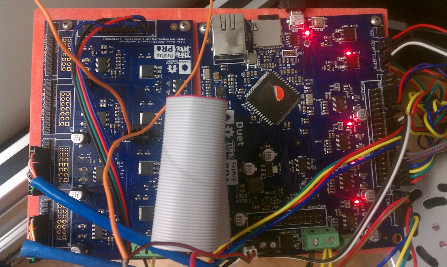
We currently do not use the web interface. All of our readings have been through pronterface and the Paneldue. We have the Duex4's power wires running to the Duet's power block and from the Duet to the PSU. Attached is a picture of the wiring setup right now. As soon as we apply power to the PSU and plug in the USB cable, as seen in the image, E0's heater turns on.
|
Re: Duet 0.6 + Duex Issue October 02, 2015 03:32PM |
Registered: 10 years ago Posts: 14,672 |
The photo helps, but I am confused. In your original post, you said that the two heater LEDs on the DueX4 were flickering. Now you say that the E0 heater LED is coming on when you power up. Is this a new problem? What does the PanelDue indicate for the head 0 current, active and standby temperatures? Can you confirm that the PanelDue shows the status as "Idle" in the top right corner, indicating that it has connected? Are you sure that there isn't a short from one of the heater wires to ground? I recently read of a heater cartridge that developed a short between one of its wires and the casing.
I have a couple of comments on your wiring, which are probably not related to the problem:
- You are using only one pair of pins on the E0 heater connector. If you are using 12V power then you should use thicker wires to the hot end heater, with each wire connected to two pins of the E0 heater connector. Or use two pairs of wires to connect the heater to the Duet, as RepRapPro does in their kits. The current rating is about 2A per pin, so a single pair of pins is sufficient only for a 12V 24W (or lower power) heater, or a 24V 48W (or lower power) heater.
- All the power wires connected to the power input terminal blocks of the Duet and DueX4 should be thicker. Running power to the Duet and from there to the X4 is OK, but the terminal block on the Duet 0.6 is rather small to accommodate two sets of thick wire. That is why I use a separate terminal block to distribute power.
Edited 1 time(s). Last edit at 10/02/2015 03:32PM by dc42.
Large delta printer [miscsolutions.wordpress.com], E3D tool changer, Robotdigg SCARA printer, Crane Quad and Ormerod
Disclosure: I design Duet electronics and work on RepRapFirmware, [duet3d.com].
|
Re: Duet 0.6 + Duex Issue December 06, 2015 09:11AM |
Registered: 8 years ago Posts: 319 |
I cannot find how to hook up my IR sensor to the DueX4. I found the table on the wiring for the PanelDue so that is not an issue. I am using the 0.6 + DueX4 configuration.
I only want the duex4 to read a 2nd thermistor (backup thermistor) for the hotend. And since the 50pin cable takes up the PIN on the expansion slot, I cannot use it for the blue cable OUT for the IR sensor. So Where do I put the blue wire OUT on the DUEx4 board.
Also since I am only using it for those 2 small things, do I need power cables going into the board (duex4)?
Edited 1 time(s). Last edit at 12/06/2015 09:11AM by DRTak.
|
Re: Duet 0.6 + Duex Issue December 06, 2015 01:46PM |
Registered: 10 years ago Posts: 14,672 |
Quote
DRTak
I cannot find how to hook up my IR sensor to the DueX4. I found the table on the wiring for the PanelDue so that is not an issue. I am using the 0.6 + DueX4 configuration.
I only want the duex4 to read a 2nd thermistor (backup thermistor) for the hotend. And since the 50pin cable takes up the PIN on the expansion slot, I cannot use it for the blue cable OUT for the IR sensor. So Where do I put the blue wire OUT on the DUEx4 board.
Also since I am only using it for those 2 small things, do I need power cables going into the board (duex4)?
From my blog at [miscsolutions.wordpress.com]:
Quote
Wiring for everything except the second extruder and second hot end loom is as before, apart from one detail. Previously, the Z probe blue wire (and white wire if you were using one of my hot end boards) were connected to the Duet expansion connector. But the expansion connector will be used to connect the DueX4 to the Duet, so this is no longer possible. If you modified the Duet as described in the previous section, you can connect the Z probe blue and white wires to the 2 new header pins provided for them. If not, then you will need to connect the blue and white Z probe wires to the 26-pin Expansion1 connector on the DueX4. The blue wire goes to the pin labelled AD12 and the white wire (if you have one) to AD14.
The blue wire referred to is the output wire from the IR sensor. The white wire is the modulation input, if the sensor has one. The pins on the DueX4 expansion connector are labelled on the underside of the board.
Regarding providing 12V or not, I suggest you measure the voltage on the terminal block of the DueX4 when power is applied to the Duet. If you don't see any voltage there, then there is nothing feeding 5V or 3.3V to the 12V rail, and you should OK leaving it not connected.
Large delta printer [miscsolutions.wordpress.com], E3D tool changer, Robotdigg SCARA printer, Crane Quad and Ormerod
Disclosure: I design Duet electronics and work on RepRapFirmware, [duet3d.com].
|
Re: Duet 0.6 + Duex Issue December 06, 2015 02:53PM |
Registered: 8 years ago Posts: 319 |
I guess what I am saying is the 50 pin cable that connects the Duet to the dUEX4 covers AD12 and AD14 Duex4 pins? So right now, I have your IR sensor (3pin connector) connected to the IR sensor. Two of the 3 output wires are connected to E Endstop (red and black wires on the picture below) on the duet0.6. The blue wire on the picture below I guess connects to the DUex4 AD12 pin but that pin is covered by the 50 pin ribbon cable? Is there a separate Pin on the EXPANSION1 pins that is useable. The same expansion slot that the paneldue connects to?
[miscsolutions.files.wordpress.com]
[miscsolutions.files.wordpress.com]
|
Re: Duet 0.6 + Duex Issue December 06, 2015 03:30PM |
Registered: 10 years ago Posts: 14,672 |
I was indeed referring to the AD12 pin on the Expansion1 connector.
Large delta printer [miscsolutions.wordpress.com], E3D tool changer, Robotdigg SCARA printer, Crane Quad and Ormerod
Disclosure: I design Duet electronics and work on RepRapFirmware, [duet3d.com].
Large delta printer [miscsolutions.wordpress.com], E3D tool changer, Robotdigg SCARA printer, Crane Quad and Ormerod
Disclosure: I design Duet electronics and work on RepRapFirmware, [duet3d.com].
|
Re: Duet 0.6 + Duex Issue December 06, 2015 03:42PM |
Registered: 8 years ago Posts: 319 |
|
Re: Duet 0.6 + Duex Issue December 06, 2015 05:44PM |
Registered: 10 years ago Posts: 14,672 |
Quote
DRTak
Quote
dc42
I was indeed referring to the AD12 pin on the Expansion1 connector.
Thanks David I see it now. Had to use reading glasses to see the AD12 pin. Sorry about that.
I have that problem too.
Large delta printer [miscsolutions.wordpress.com], E3D tool changer, Robotdigg SCARA printer, Crane Quad and Ormerod
Disclosure: I design Duet electronics and work on RepRapFirmware, [duet3d.com].
|
Re: Duet 0.6 + Duex Issue December 11, 2015 12:12PM |
Registered: 8 years ago Posts: 319 |
Quote
dc42
Quote
DRTak
I cannot find how to hook up my IR sensor to the DueX4. I found the table on the wiring for the PanelDue so that is not an issue. I am using the 0.6 + DueX4 configuration.
I only want the duex4 to read a 2nd thermistor (backup thermistor) for the hotend. And since the 50pin cable takes up the PIN on the expansion slot, I cannot use it for the blue cable OUT for the IR sensor. So Where do I put the blue wire OUT on the DUEx4 board.
Also since I am only using it for those 2 small things, do I need power cables going into the board (duex4)?
From my blog at [miscsolutions.wordpress.com]:
Quote
Wiring for everything except the second extruder and second hot end loom is as before, apart from one detail. Previously, the Z probe blue wire (and white wire if you were using one of my hot end boards) were connected to the Duet expansion connector. But the expansion connector will be used to connect the DueX4 to the Duet, so this is no longer possible. If you modified the Duet as described in the previous section, you can connect the Z probe blue and white wires to the 2 new header pins provided for them. If not, then you will need to connect the blue and white Z probe wires to the 26-pin Expansion1 connector on the DueX4. The blue wire goes to the pin labelled AD12 and the white wire (if you have one) to AD14.
The blue wire referred to is the output wire from the IR sensor. The white wire is the modulation input, if the sensor has one. The pins on the DueX4 expansion connector are labelled on the underside of the board.
Regarding providing 12V or not, I suggest you measure the voltage on the terminal block of the DueX4 when power is applied to the Duet. If you don't see any voltage there, then there is nothing feeding 5V or 3.3V to the 12V rail, and you should OK leaving it not connected.
dc42. I am still having issues. I connected the paneldue to the duex4. It works. But I cannot get the 2nd thermistor to show up on the web interface. Also, I cannot get the z probe to work correctly.
I connected (blue) wire out to ad12 on the duex4 expansion slot1. I left the red and black wires connected to the duet0.6 in the E endstops. Black ground. Red power. It just says zprobe 646 on the web interface. But doesnt register any real numbers. I then tried to guess how to wire the IR probe wires on the expansion slot 1. but I cant figure it out. I do not have a white wire. Your IR board only has GND, VCC, AND OUT. AND for me that is black ground, red vcc power, and blue wire (out).
I connected the 2nd thermistor to the E1 temp pin on the duex board as shown in the picture. GRND AND TEMP pin on the back of the duex4 board to the 2nd thermistor (backup hot end thermistor). It doesnt register. No HEATER2. Listed in the web interface.
I have connected 12v power to the duex4 and that doesnt help.
|
Re: Duet 0.6 + Duex Issue December 11, 2015 01:13PM |
Registered: 10 years ago Posts: 14,672 |
To get the second heater to register in the web interface, you need to add a M563 command in config.g to create the second tool. You may well find that your config.g file already has a second M563 command in it, but commented out. The command should be:
M563 P1 H2 D1
Regarding the IR sensor, does the red LED flash four times on power up, and then light up when it is near a target? If so, check the wire between the OUT pin of the sensor and the AD12 pin on the Expansion1 connector for continuity in case of a bad crimp connection, and check that you have correctly identified the AD12 pin on Expansion1.
Large delta printer [miscsolutions.wordpress.com], E3D tool changer, Robotdigg SCARA printer, Crane Quad and Ormerod
Disclosure: I design Duet electronics and work on RepRapFirmware, [duet3d.com].
|
Re: Duet 0.6 + Duex Issue December 11, 2015 03:24PM |
Registered: 8 years ago Posts: 319 |
Quote
dc42
To get the second heater to register in the web interface, you need to add a M563 command in config.g to create the second tool. You may well find that your config.g file already has a second M563 command in it, but commented out. The command should be:
M563 P1 H2 D1
Regarding the IR sensor, does the red LED flash four times on power up, and then light up when it is near a target? If so, check the wire between the OUT pin of the sensor and the AD12 pin on the Expansion1 connector for continuity in case of a bad crimp connection, and check that you have correctly identified the AD12 pin on Expansion1.
DC42,
I got the 2nd thermistor to work with the above config.g correction.
But oddly. I cannot get the duex4 to register AD12 on Expansion 1. I used the bare wire. Touched it to all the pins minus the 3.3v and 5v pins. No luck. I know the other pins work because when I mistakenly put the wire on GND AND RST pin it disconnected from the web interface. I also know that the Expansion 1 pins work because I can get the panel due to light up. I have no idea why AD12 is not working. I also did your ground wire thing with VSSA.
UPDATE: The only pin I did not hook up the bare wire was the pin next to the VSSA. I crossed my fingers and it works. The z probe works. I found this schematic:
[blog.think3dprint3d.com]
David. Sorry I did not mention that I have a duex4 0.2 board. But from my reading of that web page a long time ago. I thought it meant that the duex4 rev 0.2 did not require PIN39. I thought it meant that you could use AD12 on the expansion1. But I guessed wrong and got it right by connected blue wire (OUT) to the empty VSSA pin.
|
Re: Duet 0.6 + Duex Issue December 11, 2015 05:00PM |
Registered: 10 years ago Posts: 14,672 |
I'm glad you solved it! I think I see what happened. The Duet 0.6 does not have VSSA on the expansion connector. This was an oversight. In the Duet 0.8.5, the VSSA pin was added, and I see now that the pin it replaced was AD12. So on the DueX4 0.2a that pin is labelled VSSA, but when you connect it to a Duet 0.6 then it is really AD12.
If your DueX4 has a VSSA pin, then it must be a version 0.2a board. You should remove the jumper and connect the flylead as described in that blog entry.
Large delta printer [miscsolutions.wordpress.com], E3D tool changer, Robotdigg SCARA printer, Crane Quad and Ormerod
Disclosure: I design Duet electronics and work on RepRapFirmware, [duet3d.com].
|
Re: Duet 0.6 + Duex Issue December 11, 2015 07:36PM |
Registered: 8 years ago Posts: 319 |
Quote
dc42
I'm glad you solved it! I think I see what happened. The Duet 0.6 does not have VSSA on the expansion connector. This was an oversight. In the Duet 0.8.5, the VSSA pin was added, and I see now that the pin it replaced was AD12. So on the DueX4 0.2a that pin is labelled VSSA, but when you connect it to a Duet 0.6 then it is really AD12.
If your DueX4 has a VSSA pin, then it must be a version 0.2a board. You should remove the jumper and connect the flylead as described in that blog entry.
I have done what the picture shows. I connected the fly lead to the hotbed temp gnd duet0.6. Then the other lead to the VSSA grnd on the duex4.
I did have power running into the duex4. But I checked and I dont think I need power going into it. So I have since disconnected the 12v power IN.
Edited 1 time(s). Last edit at 12/11/2015 07:42PM by DRTak.
|
Re: Duet 0.6 + Duex Issue December 12, 2015 02:55AM |
Registered: 10 years ago Posts: 14,672 |
You need power running into the DueX4 if it is driving any stepper motors or heaters.
Large delta printer [miscsolutions.wordpress.com], E3D tool changer, Robotdigg SCARA printer, Crane Quad and Ormerod
Disclosure: I design Duet electronics and work on RepRapFirmware, [duet3d.com].
Large delta printer [miscsolutions.wordpress.com], E3D tool changer, Robotdigg SCARA printer, Crane Quad and Ormerod
Disclosure: I design Duet electronics and work on RepRapFirmware, [duet3d.com].
|
Re: Duet 0.6 + Duex Issue December 15, 2015 07:00PM |
Registered: 8 years ago Posts: 319 |
Quote
dc42
You need power running into the DueX4 if it is driving any stepper motors or heaters.
I am only driving a spare thermistor and the paneldue on the duex4. I do not have dual extruders yet or another heater. So no 12V connection. However,
I DID connect the 12v to the DUEX4 and checked my paneldue and I get the hue issue still. I then DISconnected the 12v power from the paneldue. And still have hue issue on the touch screen. Do I need 5v into the duex4? Is that the issue?
|
Re: Duet 0.6 + Duex Issue December 15, 2015 11:36PM |
Registered: 10 years ago Posts: 14,672 |
5V is fed to the DueX4 through the expansion connector.
Can you measure the voltage between the +5V and Gnd pins on the PanelDue connector? If the voltage there is low, that might explain the hue issue.
Large delta printer [miscsolutions.wordpress.com], E3D tool changer, Robotdigg SCARA printer, Crane Quad and Ormerod
Disclosure: I design Duet electronics and work on RepRapFirmware, [duet3d.com].
|
Re: Duet 0.6 + Duex Issue December 17, 2015 10:14PM |
Registered: 8 years ago Posts: 319 |
Quote
dc42
5V is fed to the DueX4 through the expansion connector.
Can you measure the voltage between the +5V and Gnd pins on the PanelDue connector? If the voltage there is low, that might explain the hue issue.
Ok. Very odd. Measured it with 12v power coming into the duex4. It read 1.5v at Pin1 on expansion 1 pins. Why is that? Did I not set a jumper right somewhere?
|
Re: Duet 0.6 + Duex Issue December 18, 2015 03:13AM |
Registered: 10 years ago Posts: 14,672 |
How are you feeding 12V power to the X4? Do not run separate wires from it back to the power supply. Instead, put a connector block close to the Duet and DueX4 to distribute the power, and run short thick solid core wires from it to the Duet and to the DueX4. I used the cores from a length of 30A ring main cable. See my blog entry on converting the Ormerod to dual extrusion.
Large delta printer [miscsolutions.wordpress.com], E3D tool changer, Robotdigg SCARA printer, Crane Quad and Ormerod
Disclosure: I design Duet electronics and work on RepRapFirmware, [duet3d.com].
Large delta printer [miscsolutions.wordpress.com], E3D tool changer, Robotdigg SCARA printer, Crane Quad and Ormerod
Disclosure: I design Duet electronics and work on RepRapFirmware, [duet3d.com].
|
Re: Duet 0.6 + Duex Issue December 19, 2015 12:17AM |
Registered: 8 years ago Posts: 319 |
Quote
dc42
How are you feeding 12V power to the X4? Do not run separate wires from it back to the power supply. Instead, put a connector block close to the Duet and DueX4 to distribute the power, and run short thick solid core wires from it to the Duet and to the DueX4. I used the cores from a length of 30A ring main cable. See my blog entry on converting the Ormerod to dual extrusion.
PANELDUE ISSUE: So like this picture attached. The black and yellow wire in the picture. From the power block in the duet to the power block in the duex4? I did run a separate line from the power supply to the duex4. Another separate line goes into the duet 0.6.
UPDATE FOR ENDSTOP ISSUE. I have a solution for below. I will not delete the text below for my own future reference and to help others. My bad Y endstop issue was caused by miswiring of the IR sensor. The red was connected to ground and the black was connected to red. This caused the Y endstop to not work.
I have another big issue. I cannot figure it out. My Y endstop. doesnt work anymore. I was having issues with it for a bit. During homing, the Y endstop would violently crash up into the tower. But after 5min it would stop and home correctly. I thought it was just that the system had to heat up a bit. But I took the whole system apart and looked at all the wiring. Nothing wrong. I then remounted it all onto the top of the Kossel. I thought that it was a bad mechanical endstop. So I tested a new endstop at the Y location. Same thing. It doesnt read. It says NOT STOPPED after a M119 command even if the trigger is pressed. I used 2 new wires and a new endstop to make sure it wasnt the wiring. And its not. Oddly the lights on the duet go on and off when I push the endstop. However it doesnt read. I tried Internet explorer instead of Chrome since I thought maybe it was a browser issue? It does the same thing on Explorer. The X and Z axis work but only if I have the wiring exact. The yellow wire from the endstop has to attach to the yellow wire on the duet. And the black wire from the endstop has to attach to the black wire on the duet as noted in the picture. If they are not correctly oriented the X and Z will not read. Understanding that this is the case, I swapped wires for the Y axis but it doesnt help. I tried every permutation of the 4 wires on the Y axis and none work. Another odd thing, If I mismatch the wires and can get an inverted signal to work. The duet red light will be off for the Y axis. If the triger is pressed on the endstop the red light comes on. When the trigger is NOT pressed after an M119 command it says AT MAX STOP. When I PRESS the switch it says NOT STOPPED. I am LOST since the system is reading the endstop but not correctly..
Edited 4 time(s). Last edit at 12/19/2015 11:18AM by DRTak.
|
Re: Duet 0.6 + Duex Issue December 20, 2015 10:19AM |
Registered: 8 years ago Posts: 319 |
|
Re: Duet 0.6 + Duex Issue December 20, 2015 10:37AM |
Registered: 10 years ago Posts: 14,672 |
Quote
DRTak
I searched the web and cannot find any information on how to create Macros for the duet web interface?
I guess I need to add that to the wiki pages. This is how you do it:
1. Create a directory on the SD card called /macros.
2. Populate it with files who name is the text you want to appear on the web interface and on PanelDue (no need for a .g or .gcode extension), and whose contents are the gcodes you want to run. You can upload these through the Macros tab on the web interface.
The firmware automatically does a push before running a macro file, so certain parameters get saved and restored, e.g. feed rate, relative/absolute movement, and relative/absolute extrusion.
Large delta printer [miscsolutions.wordpress.com], E3D tool changer, Robotdigg SCARA printer, Crane Quad and Ormerod
Disclosure: I design Duet electronics and work on RepRapFirmware, [duet3d.com].
|
Re: Duet 0.6 + Duex Issue December 20, 2015 10:46AM |
Registered: 8 years ago Posts: 319 |
Quote
dc42
Quote
DRTak
I searched the web and cannot find any information on how to create Macros for the duet web interface?
I guess I need to add that to the wiki pages. This is how you do it:
1. Create a directory on the SD card called /macros.
2. Populate it with files who name is the text you want to appear on the web interface and on PanelDue (no need for a .g or .gcode extension), and whose contents are the gcodes you want to run. You can upload these through the Macros tab on the web interface.
The firmware automatically does a push before running a macro file, so certain parameters get saved and restored, e.g. feed rate, relative/absolute movement, and relative/absolute extrusion.
dc42. thanks again. I will try this.
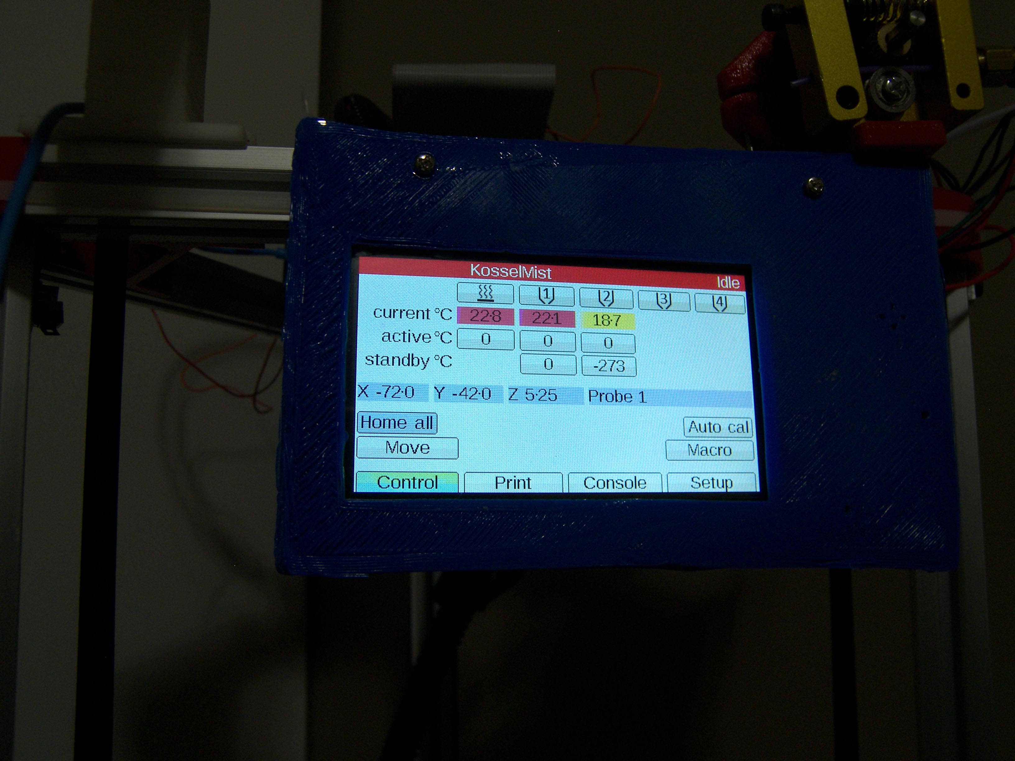
Next, I did hook up a GND and PWR lead from the duet0.6 to the duex4. The paneldue now gets 4.6v instead of 1.6v. But I still have a hue issue. Im wondering if this is normal. Hotend one is colored red (active) and says 22.7deg C. BUT 1/4 of the red is purple. When I switch it to standby 1st 1/4 of the yellow is dull yellow. The other 3/4 is bright yellow. Is there anyway to adjust the LCD displays contrast? Same thing happens when I turn on BED to active or standby. I understand that this whole issue is a cosmetic thing but I want to make sure Im not frying my paneldue.
|
Re: Duet 0.6 + Duex Issue December 20, 2015 11:21AM |
Registered: 10 years ago Posts: 14,672 |
Can you post a photo? Where did you get the display from?
Large delta printer [miscsolutions.wordpress.com], E3D tool changer, Robotdigg SCARA printer, Crane Quad and Ormerod
Disclosure: I design Duet electronics and work on RepRapFirmware, [duet3d.com].
Large delta printer [miscsolutions.wordpress.com], E3D tool changer, Robotdigg SCARA printer, Crane Quad and Ormerod
Disclosure: I design Duet electronics and work on RepRapFirmware, [duet3d.com].
|
Re: Duet 0.6 + Duex Issue December 20, 2015 11:30AM |
Registered: 8 years ago Posts: 319 |
Quote
dc42
Can you post a photo? Where did you get the display from?
I have attached a picture. I have rebooted the system and now the hue is 1/8 of the Red color coding. Maybe hard to tell from the compressed picture. I had to compress it to fit the 674k limit.
I got the whole paneldue kit on ebay. The panel due was new. The duet was listed as new. The duex4 was new and untouched. So far I just have one issue with the hue.
Again I know the color is a cosmetic issue.
Edited 3 time(s). Last edit at 12/21/2015 10:12AM by DRTak.

Sorry, only registered users may post in this forum.