DIY Tiny OLED I2C full graphics controller
Posted by enif
|
Re: DIY Tiny OLED I2C full graphics controller December 11, 2017 02:12AM |
Registered: 9 years ago Posts: 590 |
The SCAD file is commented - but I am sorry, no other explanations for it are available.
And I admit that the technique I used here is somewhat untypical for OpenScad: Essentially, each object consists just of two arrays of blocks, the first one are additive blocks, the second one cavities that are to be cut out. A normal "cube" type block consists just of two entries: the origin point and the size. A cylindrical block consist of the origin followed by an array [direction, radius, height] where direction is (-1 for X, -2 for Y, -3 for Z). Finally there are also optional 3rd , 4th and 5th entries in each block which can be used to specify the value of $fn (i.e. the number of corners used to approximate the cylinder), the level of the block (lower levels are generated/subtracted first) and a condition string (allowing blocks to be only generated under certain conditions).
With this information and the comments in the block list you should at least be able to understand the structure of the objects.
While this is a rather efficient way of coding, I am not sure if it is a good starting point for someone just beginning to learn OpenScad. In this case traditional coding with explicit
calls to cube(), cylinder(), translate(), difference(), etc. is probably much easier...
|
Re: DIY Tiny OLED I2C full graphics controller December 29, 2017 03:00AM |
Registered: 6 years ago Posts: 3 |
Quote
enif
As for the I2C problem on the Arduino Due that caused some conflict when activating simultaneously the I2C OLED (using the U8glib I2C routines) and the I2C EEPROM (using Arduino's Wire.h), I have made some progress:
I removed the '//' from the (3 each) commented out statements "//u8g->pin_list[U8G_PI_SET_A0] = 1;" and "// u8g_i2c_stop();" in file U8glib/utility/u8g_com_arduino_ssd_i2c.c :
$diff u8g_com_arduino_ssd_i2c.c.ori u8g_com_arduino_ssd_i2c.c
125c125
<       //u8g->pin_list[U8G_PI_SET_A0] = 1;
---
>       u8g->pin_list[U8G_PI_SET_A0] = 1;
130c130
<       // u8g_i2c_stop();
---
>       u8g_i2c_stop();
134c134
<       //u8g->pin_list[U8G_PI_SET_A0] = 1;
---
>       u8g->pin_list[U8G_PI_SET_A0] = 1;
146c146
<       // u8g_i2c_stop();
---
>       u8g_i2c_stop();
150c150
<       //u8g->pin_list[U8G_PI_SET_A0] = 1;
---
>       u8g->pin_list[U8G_PI_SET_A0] = 1;
163c163
<       // u8g_i2c_stop();
---
>       u8g_i2c_stop();
After recompiling Marlin4Due with this change the Arduino Due the conflict seems resolved and it can now access the I2C EEPROM (after having it activated in Configuration.h of course) while using the I2C OLED display - so far without any problem

I tried this with marlin 2.0 bugfix and ramps_fd_v2 (tinyoled uncommented), but display and eeprom are not working at the same time. Eeprom only is working. Display only is not working, but it is working for a second when i press disconnect and connect in pronterface. then it goes black again.
Does anyone have this working with Due?
|
Re: DIY Tiny OLED I2C full graphics controller July 10, 2018 05:20AM |
Registered: 6 years ago Posts: 69 |
Hi all,
I've solved the issue for the EEPROM I2C on Arduino Due (RAMPS4DUE project) in a very easy way.
I've simply moved the EEPROM on the 2nd I2C port available on the Due ( SCL1 SDA1) and made few modification on the Marlin4due firmware:
- Connect the EEPROM on the 2nd I2C, dont' forget to add a couple of 1.5K pull up resistors between SCL1 to 3.3v and SDA1 to 3.3v (the pull up resistors are already implemented on the 1st I2C (D20 and D21) of the Due board.
- Modify the Configuration.h to add the option for the 2nd I2C, the red one, in the EEPROM section:
- Now you have to modify the HAL.ccp to add the new option for the 2nd I2C (in few words we have to use wire1 instead of wire to address the EEOROM on 2nd I2C). Replace the lines between the "//eeprom" and "//Timers" and put the below code:
Now you can use both I2C OLED and I2C EEPROM at the same time.
Bye
Edited 1 time(s). Last edit at 07/11/2018 01:30AM by Skytter.
- Geeetech I3 Pro B "Tuning" GT2560 A+ con sesto Stepper Driver e 3 estrusori - Doppio Alimentatore e Scheda Mosfet per l'HeatBed - Dondolo per I3 Pro B - Diamond HotEnd color mixing - Mk8 Extruder 0.2 nozzle.
- TronXY X5S con Ruramps4d in fase di test.
- Progetto "MiniMaker" full stroke 200x200x180 printer in a 300x300x300 cube.
My Thingiverse: [www.thingiverse.com]
I've solved the issue for the EEPROM I2C on Arduino Due (RAMPS4DUE project) in a very easy way.
I've simply moved the EEPROM on the 2nd I2C port available on the Due ( SCL1 SDA1) and made few modification on the Marlin4due firmware:
- Connect the EEPROM on the 2nd I2C, dont' forget to add a couple of 1.5K pull up resistors between SCL1 to 3.3v and SDA1 to 3.3v (the pull up resistors are already implemented on the 1st I2C (D20 and D21) of the Due board.
SDA1        3.3V       SCL1
 |           |          |
 |           |          |
 o--[1.5k]---o          |
             |          |
             |          |
             o--[1.5k]--o
- Modify the Configuration.h to add the option for the 2nd I2C, the red one, in the EEPROM section:
#ifdef EEPROM_SETTINGS
  // To disable EEPROM Serial responses and decrease program space by ~1700 byte: comment this out:
  #define EEPROM_CHITCHAT // Please keep turned on if you can.
  #define EEPROM_ON_2ND_I2C // EEPROM CHIP ON second I2C for Arduino Due
  #endif
- Now you have to modify the HAL.ccp to add the new option for the 2nd I2C (in few words we have to use wire1 instead of wire to address the EEOROM on 2nd I2C). Replace the lines between the "//eeprom" and "//Timers" and put the below code:
// --------------------------------------------------------------------------
// eeprom
// --------------------------------------------------------------------------


static bool eeprom_initialised = false;
static uint8_t eeprom_device_address = 0x50;

#ifdef EEPROM_ON_2ND_I2C

static void eeprom_init(void) {
	if (!eeprom_initialised) {
		Wire1.begin();
		eeprom_initialised = true;
	}
}

void eeprom_write_byte(unsigned char *pos, unsigned char value) {
	unsigned eeprom_address = (unsigned) pos;

	eeprom_init();

	Wire1.beginTransmission(eeprom_device_address);
	Wire1.write((int)(eeprom_address >> 8));   // MSB
	Wire1.write((int)(eeprom_address & 0xFF)); // LSB
  Wire1.write(value);
	Wire1.endTransmission();

	// wait for write cycle to complete
	// this could be done more efficiently with "acknowledge polling"
	delay(5);
}


unsigned char eeprom_read_byte(unsigned char *pos) {
	byte data = 0xFF;
	unsigned eeprom_address = (unsigned) pos;

	eeprom_init ();

	Wire1.beginTransmission(eeprom_device_address);
	Wire1.write((int)(eeprom_address >> 8));   // MSB
	Wire1.write((int)(eeprom_address & 0xFF)); // LSB
	Wire1.endTransmission();
	Wire1.requestFrom(eeprom_device_address, (byte)1);
	if (Wire1.available())
		data = Wire1.read();
	return data;
}

#else

static void eeprom_init(void) {
	if (!eeprom_initialised) {
		Wire.begin();
		eeprom_initialised = true;
	}
}

void eeprom_write_byte(unsigned char *pos, unsigned char value) {
	unsigned eeprom_address = (unsigned) pos;

	eeprom_init();

	Wire.beginTransmission(eeprom_device_address);
	Wire.write((int)(eeprom_address >> 8));   // MSB
	Wire.write((int)(eeprom_address & 0xFF)); // LSB
    Wire.write(value);
	Wire.endTransmission();

	// wait for write cycle to complete
	// this could be done more efficiently with "acknowledge polling"
	delay(5);
}


unsigned char eeprom_read_byte(unsigned char *pos) {
	byte data = 0xFF;
	unsigned eeprom_address = (unsigned) pos;

	eeprom_init ();

	Wire.beginTransmission(eeprom_device_address);
	Wire.write((int)(eeprom_address >> 8));   // MSB
	Wire.write((int)(eeprom_address & 0xFF)); // LSB
	Wire.endTransmission();
	Wire.requestFrom(eeprom_device_address, (byte)1);
	if (Wire.available())
		data = Wire.read();
	return data;
}
#endif

// --------------------------------------------------------------------------
// Timers
// --------------------------------------------------------------------------
Now you can use both I2C OLED and I2C EEPROM at the same time.
Bye
Edited 1 time(s). Last edit at 07/11/2018 01:30AM by Skytter.
- Geeetech I3 Pro B "Tuning" GT2560 A+ con sesto Stepper Driver e 3 estrusori - Doppio Alimentatore e Scheda Mosfet per l'HeatBed - Dondolo per I3 Pro B - Diamond HotEnd color mixing - Mk8 Extruder 0.2 nozzle.
- TronXY X5S con Ruramps4d in fase di test.
- Progetto "MiniMaker" full stroke 200x200x180 printer in a 300x300x300 cube.
My Thingiverse: [www.thingiverse.com]
|
Re: DIY Tiny OLED I2C full graphics controller September 20, 2018 03:06AM |
Registered: 5 years ago Posts: 3 |

|
Re: DIY Tiny OLED I2C full graphics controller September 20, 2018 12:55PM |
Registered: 9 years ago Posts: 590 |
|
Re: DIY Tiny OLED I2C full graphics controller September 22, 2018 12:23PM |
Registered: 5 years ago Posts: 3 |
Hi
It is MKS gen 1.4 display is 1.3"
latest version of marlin 1.8.5
S.T.E.V.E - CoreXY 3D Printer - [www.thingiverse.com]
It is MKS gen 1.4 display is 1.3"
latest version of marlin 1.8.5
S.T.E.V.E - CoreXY 3D Printer - [www.thingiverse.com]
|
Re: DIY Tiny OLED I2C full graphics controller September 23, 2018 02:32AM |
Registered: 9 years ago Posts: 590 |
What kind of "1.3 inch oled display" do you have? Unfortunately you don't give any more details on that part - which is the crucial one to answer your question....
Did you really build the "Tiny OLED I2C" controller which this thread is about?
If yes, which version of the PCB and which version of the OLED? (Some I2C OLEDs have different pinouts...)
If no, what exactly do you mean when you say "1.3 inch OLED"? Please show some photos of your hardware.
Did you really build the "Tiny OLED I2C" controller which this thread is about?
If yes, which version of the PCB and which version of the OLED? (Some I2C OLEDs have different pinouts...)
If no, what exactly do you mean when you say "1.3 inch OLED"? Please show some photos of your hardware.
|
Re: DIY Tiny OLED I2C full graphics controller September 23, 2018 03:37AM |
Registered: 5 years ago Posts: 3 |
Hi
I don t have hardware problem
pins are directly conected to the mainboard same as it is shown in electrical sheme in first post
I just don t know what to put where in marlin diff is a little bit confusing
there is no:
dogm_lcd_implementation.h
Edited 1 time(s). Last edit at 09/23/2018 04:04AM by mdg1.
|
Re: DIY Tiny OLED I2C full graphics controller September 23, 2018 07:55AM |
Registered: 9 years ago Posts: 590 |
|
Re: DIY Tiny OLED I2C full graphics controller September 23, 2018 10:14AM |
Registered: 9 years ago Posts: 590 |
I now downloaded the current version 1.1.9 of Marlin and configured it for my TINYOLED on RAMPS. I needed to change the files Configuration.h, Conditionals_LCD.h and pins_RAMPS.h as follows:
Edited 1 time(s). Last edit at 09/23/2018 10:22AM by enif.
diff Configuration.h.ori Configuration.h
*** Configuration.h.ori	2018-09-23 15:49:49.410579191 +0200
--- Configuration.h	2018-09-23 15:51:19.728792937 +0200
***************
*** 1531,1536 ****
--- 1531,1540 ----
  //
  //#define REPRAP_DISCOUNT_SMART_CONTROLLER

+ //#define U8GLIB_SH1106   // used for most 1.3" OLEDs (default for TINYOLED)
+ //#define U8GLIB_SSD1306  // used for most 0.96" OLEDs
+ #define TINYOLED
+
  //
  // ULTIMAKER Controller.
  //
diff Conditionals_LCD.h.ori Conditionals_LCD.h
*** Conditionals_LCD.h.ori	2018-09-23 15:48:49.055772809 +0200
--- Conditionals_LCD.h	2018-09-23 16:06:14.335230093 +0200
***************
*** 88,93 ****
--- 88,106 ----
      #define SD_DETECT_INVERTED
    #endif

+
+ #elif ENABLED(TINYOLED)
+
+   #ifndef U8GLIB_SSD1306   // define U8GLIB_SSD1306 in Configuration.h if not using SH1106 version
+     #define U8GLIB_SH1106 // SSD1306 and SH1106 are similar, but have slightly different horizontal shift
+   #endif
+   #define ULTIPANEL
+   #define NEWPANEL
+   #define ULTRA_LCD
+   #define DOGLCD
+   #define REVERSE_ENCODER_DIRECTION
+   #define REVERSE_MENU_DIRECTION
+
  #elif ENABLED(OLED_PANEL_TINYBOY2)

    #define U8GLIB_SSD1306
***************
*** 244,249 ****
--- 257,263 ----
  #elif ENABLED(miniVIKI) || ENABLED(VIKI2) \
     || ENABLED(ELB_FULL_GRAPHIC_CONTROLLER) \
     || ENABLED(OLED_PANEL_TINYBOY2) \
+    || ENABLED(TINYOLED) \
     || ENABLED(BQ_LCD_SMART_CONTROLLER) \
     || ENABLED(LCD_I2C_PANELOLU2) \
     || ENABLED(REPRAP_DISCOUNT_SMART_CONTROLLER)
diff pins_RAMPS.h.ori pins_RAMPS.h
*** pins_RAMPS.h.ori	2018-09-23 15:45:57.975156042 +0200
--- pins_RAMPS.h	2018-09-23 15:47:03.653857233 +0200
***************
*** 431,436 ****
--- 431,445 ----
          #define LCD_BACKLIGHT_PIN 39
        #endif

+     #elif ENABLED(TINYOLED)
+       #define BTN_EN1 31
+       #define BTN_EN2 33
+       #define BTN_ENC 35
+       #define BEEPER_PIN 37
+       #define LCD_SDSS 53
+       #define SD_DETECT_PIN -1
+       #define KILL_PIN -1
+
      #elif ENABLED(REPRAPWORLD_GRAPHICAL_LCD)

        #define BTN_EN1           64
Edited 1 time(s). Last edit at 09/23/2018 10:22AM by enif.
|
Re: DIY Tiny OLED I2C full graphics controller September 28, 2018 11:28PM |
Registered: 6 years ago Posts: 110 |
I am trying to build one of these up as well.
Regarding Marlin- is the config file changes listed in the above post the same as the option for this entry for graphics control panels in Configuration.h file?
This is from 1.1.8.
// TinyBoy2 128x64 OLED / Encoder Panel
//
//#define OLED_PANEL_TINYBOY2
I am not good with code and am having trouble following the files and calls.
thanks in advance
sinneD
Edited 1 time(s). Last edit at 09/29/2018 12:20AM by sinned.
|
Re: DIY Tiny OLED I2C full graphics controller September 29, 2018 03:59AM |
Registered: 9 years ago Posts: 590 |
|
Re: DIY Tiny OLED I2C full graphics controller September 29, 2018 11:19AM |
Registered: 6 years ago Posts: 110 |
enif-
thanks for the reply. i will do my best with the above edits
EDIT: I used the above edits in a fresh download of 1.1.9. The line numbers were close, not exactly perfect, but not far off.
I do question a couple of lines- in the first part of the diff, you added commented lines for U8GLIB entries? are they needed if they are commented?
my display works but my buzzer doesn't- could be my buzzer, but having the oled and encoder is tops!
EDIT 2: turns out its NOT the piezo buzzer, but Marlin config. You have to enable the following lines- ~ line number 1510 to get feedback sound. I can not remember previous versions settings.
you will also have to adjut the frequency and duration to make them audible. I used MS=100 and f=5000
sinneD
Edited 5 time(s). Last edit at 09/30/2018 02:52PM by sinned.
thanks for the reply. i will do my best with the above edits
EDIT: I used the above edits in a fresh download of 1.1.9. The line numbers were close, not exactly perfect, but not far off.
I do question a couple of lines- in the first part of the diff, you added commented lines for U8GLIB entries? are they needed if they are commented?
my display works but my buzzer doesn't- could be my buzzer, but having the oled and encoder is tops!
diff Configuration.h.ori Configuration.h
*** Configuration.h.ori	2018-09-23 15:49:49.410579191 +0200
--- Configuration.h	2018-09-23 15:51:19.728792937 +0200
***************
*** 1531,1536 ****
--- 1531,1540 ----
  //
  //#define REPRAP_DISCOUNT_SMART_CONTROLLER

+ //#define U8GLIB_SH1106   // used for most 1.3" OLEDs (default for TINYOLED)
+ //#define U8GLIB_SSD1306  // used for most 0.96" OLEDs
+ #define TINYOLED
+
EDIT 2: turns out its NOT the piezo buzzer, but Marlin config. You have to enable the following lines- ~ line number 1510 to get feedback sound. I can not remember previous versions settings.
// If you have a speaker that can produce tones, enable it here.
// By default Marlin assumes you have a buzzer with a fixed frequency.
//
#define SPEAKER

//
// The duration and frequency for the UI feedback sound.
// Set these to 0 to disable audio feedback in the LCD menus.
//
// Note: Test audio output with the G-Code:
//  M300 S P
//
#define LCD_FEEDBACK_FREQUENCY_DURATION_MS 100
#define LCD_FEEDBACK_FREQUENCY_HZ 5000
you will also have to adjut the frequency and duration to make them audible. I used MS=100 and f=5000
sinneD
Edited 5 time(s). Last edit at 09/30/2018 02:52PM by sinned.
|
Re: DIY Tiny OLED I2C full graphics controller October 27, 2018 02:44PM |
Registered: 7 years ago Posts: 58 |
|
Re: DIY Tiny OLED I2C full graphics controller January 20, 2019 08:18AM |
Registered: 5 years ago Posts: 1 |
Hi, i hope someone can help me.
I have a anet board and a 0'96 oled on it (sda & scl on LCD pin 8 & 10)
In configuration.h i selected my anet board and defined U8glib_ssd1306, oled works fine.
But my problem is that i have absolutley no idea how i must edit anything for my rotary encoder :/
I have a anet board and a 0'96 oled on it (sda & scl on LCD pin 8 & 10)
In configuration.h i selected my anet board and defined U8glib_ssd1306, oled works fine.
But my problem is that i have absolutley no idea how i must edit anything for my rotary encoder :/
|
Re: DIY Tiny OLED I2C full graphics controller January 20, 2019 03:58PM |
Registered: 9 years ago Posts: 590 |
I don't know the Anet board nor how exactly you have connected the encoder and the buzzer to the board.
But what you need to do is in pins_ANET_10.h (or whatever the pins file for your board is) you need to
define the pin numbers for the 3 encoder pins BTN_EN1, BTN_EN2, BTN_ENC and for the buzzer pin BEEPER_PIN.
But what you need to do is in pins_ANET_10.h (or whatever the pins file for your board is) you need to
define the pin numbers for the 3 encoder pins BTN_EN1, BTN_EN2, BTN_ENC and for the buzzer pin BEEPER_PIN.
|
Re: DIY Tiny OLED I2C full graphics controller January 25, 2019 01:54PM |
Registered: 5 years ago Posts: 4 |
|
Re: DIY Tiny OLED I2C full graphics controller January 26, 2019 08:14AM |
Registered: 9 years ago Posts: 590 |
Quote
juansuarez
I have been trying for 3 months to connect the oled but the marlin gives me 8mhz errors
Could you please explain your problem more specifically:
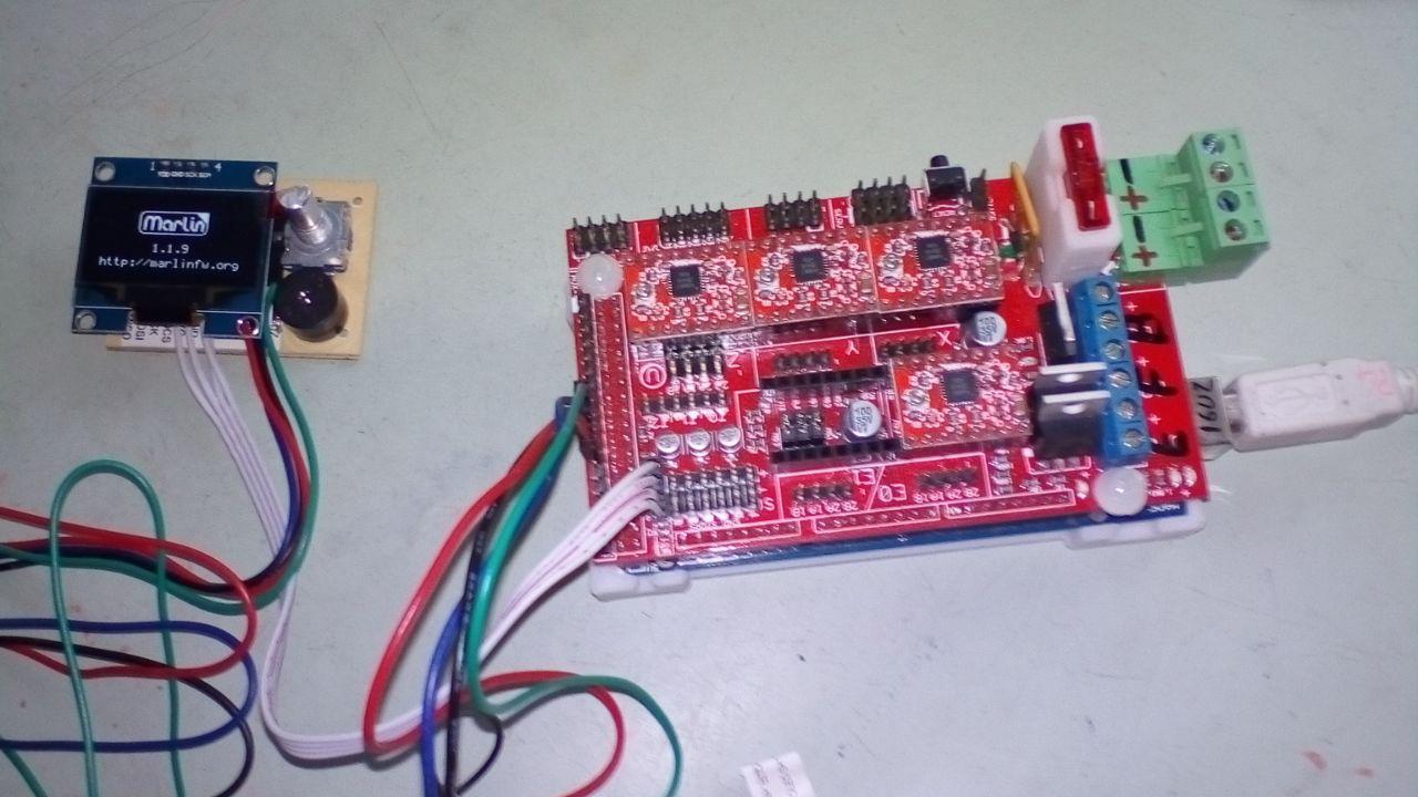
- Where do you get "8MHz errors", what is the exact error message and from which program?
- How did you connect you OLED? Pictures?
- Which version of the Tiny OLED do you have? Is it the one described here? or one bought from China? ... or just a bare OLED?
|
Re: DIY Tiny OLED I2C full graphics controller January 26, 2019 08:34AM |
Admin Registered: 13 years ago Posts: 6,998 |
|
Re: DIY Tiny OLED I2C full graphics controller January 26, 2019 08:35AM |
Registered: 9 years ago Posts: 590 |
@juansuarez:
Here is how I modified Marlin 1.1.9 for my Tiny OLED on the Sanguinololu:
In Configuration.h add a line "#define TINYOLED" and make sure that you don't have any other display controllers defined.
Apply the following changes in pins_SANGUINOLOLU_11.h:
Apply the following changes in Conditionals_LCD.h:
These are only the changes for configuring the Tiny OLED, not including any changes specific to the Sanguinololu and the printer itself.
Here is how I modified Marlin 1.1.9 for my Tiny OLED on the Sanguinololu:
In Configuration.h add a line "#define TINYOLED" and make sure that you don't have any other display controllers defined.
Apply the following changes in pins_SANGUINOLOLU_11.h:
*** pins_SANGUINOLOLU_11.h.ori	2018-12-04 10:37:15.101313000 +0100
--- pins_SANGUINOLOLU_11.h	2018-12-04 10:47:03.641419000 +0100
***************
*** 262,267 ****
--- 269,285 ----
      #define BTN_EN1             -1
      #define BTN_EN2             -1

+     #elif ENABLED(TINYOLED)
+       #ifdef BTN_EN1
+         #undef BTN_EN1
+         #undef BTN_EN2
+       #endif
+       #define BTN_EN1 30  // A1 - rotary encoder A
+       #define BTN_EN2 29  // A2 - rotary encoder B
+       #define BTN_ENC 28  // A3 - rotary encoder push switch
+       #define BEEPER_PIN  10  // RX1 - piezo beeper
+       #define LCD_SDSS 31     // SD Card SS pin
+
    #else  // !LCD_I2C_PANELOLU2 && !LCD_FOR_MELZI && !ZONESTAR_LCD

      #define BTN_ENC             16
Apply the following changes in Conditionals_LCD.h:
*** Conditionals_LCD.h.ori	2018-12-02 10:30:33.677927000 +0100
--- Conditionals_LCD.h	2018-12-02 10:31:20.713003000 +0100
***************
*** 88,93 ****
--- 88,106 ----
      #define SD_DETECT_INVERTED
    #endif

+
+ #elif ENABLED(TINYOLED)
+
+   #ifndef U8GLIB_SSD1306   // define U8GLIB_SSD1306 in Configuration.h if not using SH1106 version
+     #define U8GLIB_SH1106 // SSD1306 and SH1106 are similar, but have slightly different horizontal shift
+   #endif
+   #define ULTIPANEL
+   #define NEWPANEL
+   #define ULTRA_LCD
+   #define DOGLCD
+   #define REVERSE_ENCODER_DIRECTION
+   #define REVERSE_MENU_DIRECTION
+
  #elif ENABLED(OLED_PANEL_TINYBOY2)

    #define U8GLIB_SSD1306
***************
*** 244,249 ****
--- 257,263 ----
  #elif ENABLED(miniVIKI) || ENABLED(VIKI2) \
     || ENABLED(ELB_FULL_GRAPHIC_CONTROLLER) \
     || ENABLED(OLED_PANEL_TINYBOY2) \
+    || ENABLED(TINYOLED) \
     || ENABLED(BQ_LCD_SMART_CONTROLLER) \
     || ENABLED(LCD_I2C_PANELOLU2) \
     || ENABLED(REPRAP_DISCOUNT_SMART_CONTROLLER)
These are only the changes for configuring the Tiny OLED, not including any changes specific to the Sanguinololu and the printer itself.
|
Re: DIY Tiny OLED I2C full graphics controller January 31, 2019 11:06PM |
Registered: 5 years ago Posts: 4 |
hello thank you all
this problem is the one that I have
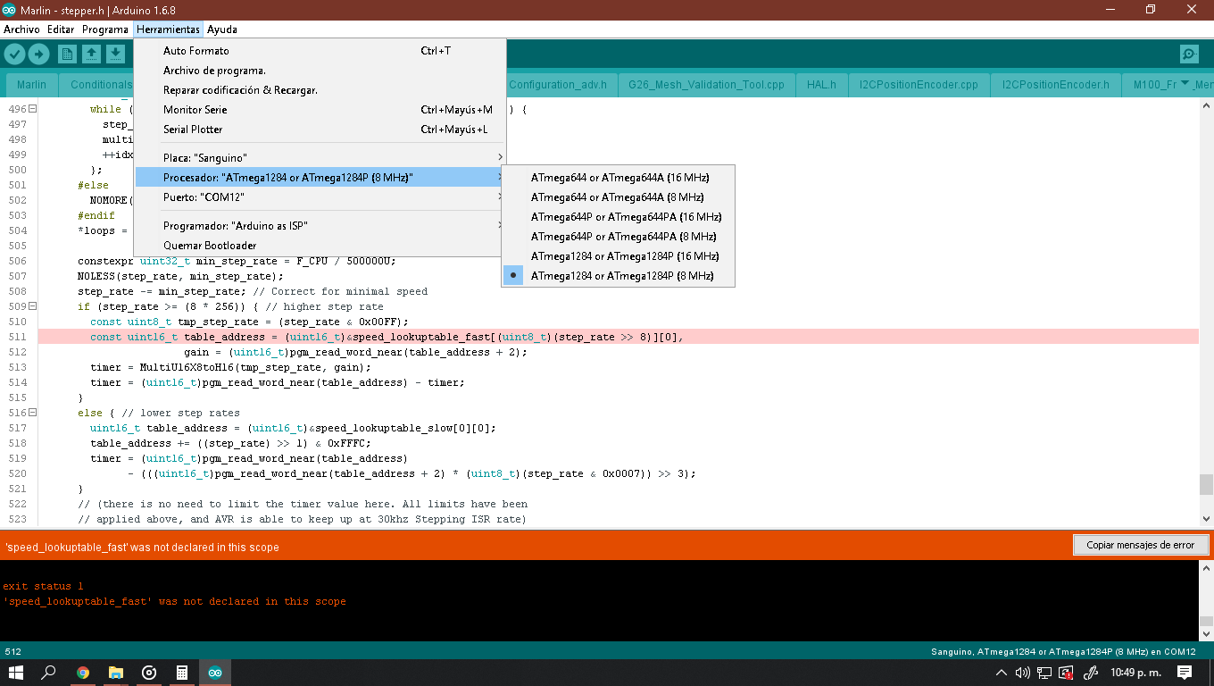
const uint16_t table_address = (uint16_t) & speed_lookuptable_fast [(uint8_t) (step_rate >> 8)] [0],
gain = (uint16_t) pgm_read_word_near (table_address + 2);
I am very new with sanguinololu
I have not been able to solve the problem
Thank you
this problem is the one that I have
const uint16_t table_address = (uint16_t) & speed_lookuptable_fast [(uint8_t) (step_rate >> 8)] [0],
gain = (uint16_t) pgm_read_word_near (table_address + 2);
I am very new with sanguinololu
I have not been able to solve the problem
Thank you
|
Re: DIY Tiny OLED I2C full graphics controller January 31, 2019 11:12PM |
Registered: 5 years ago Posts: 4 |
Hello
when I upload other programs to sanguinololu there is no problem but with marlin if and I am pointing the plate well the number 62 and the marlin does not generate problem when I choose atmega1284 16mhz but when I choose atmega1284 8mhz if there is
Thank you
when I upload other programs to sanguinololu there is no problem but with marlin if and I am pointing the plate well the number 62 and the marlin does not generate problem when I choose atmega1284 16mhz but when I choose atmega1284 8mhz if there is
Thank you
|
Re: DIY Tiny OLED I2C full graphics controller February 01, 2019 03:20AM |
Admin Registered: 13 years ago Posts: 6,998 |
@juansuarez do not choose 8mhz. the sanguinololu board is 16mhz.
but if you really want to...
look in speed_lookuptable.h
the file consists of a large block of data in a if statement
#if F_CPU == 16000000 // ie 16mhz
const uint16_t speed_lookuptable_fast[256][2] PROGMEM = {
...
const uint16_t speed_lookuptable_slow[256][2] PROGMEM = {
...
#elif F_CPU == 20000000 //ie 20mhz
const uint16_t speed_lookuptable_fast[256][2] PROGMEM = {
...
const uint16_t speed_lookuptable_slow[256][2] PROGMEM = {
...
you would need to setup a section starting with
#elif F_CPU == 8000000 //ie 8mhz
with the correct values for the two lookup tables.
use the tool createSpeedLookupTable.py from [github.com]
eg python createSpeedLookupTable.py --cpu-freq 8 --divider 8
But if you don't have a 8mhz Crystal or resonator, it may compile, but it will not work, as the serial baud rates will be at the wrong frequency.
Edited 6 time(s). Last edit at 02/01/2019 04:47AM by Dust.
|
Re: DIY Tiny OLED I2C full graphics controller March 01, 2019 06:32PM |
Registered: 5 years ago Posts: 4 |
|
Re: DIY Tiny OLED I2C full graphics controller April 24, 2019 05:09PM |
Registered: 6 years ago Posts: 110 |
enif-
are you using this on Marlin 2.0 8bit or 32bit? i was hoping to switch to 32bit with ReArm but I am a little stumped right now how to configure it.
ReArm does use SPI - can we use that per Biachifan's post on page 2?
There is the 'universal adapter' using a arduino nano as a go between but that seems to go against the simplicity of the TinyOLED.
[github.com]
Here is the panacutt 'support' page-
ReArm Display Docs
And here is the Viki2 suport page- Viki2 Docs
One can use the RRD smart adapter controller adapter with ReArm - can we hotwire those pins to the display .

|
Re: DIY Tiny OLED I2C full graphics controller April 25, 2019 11:14AM |
Registered: 9 years ago Posts: 590 |
Quote
sinned
are you using this on Marlin 2.0 8bit or 32bit? i was hoping to switch to 32bit with ReArm but I am a little stumped right now how to configure it.
ReArm does use SPI - can we use that per Biachifan's post on page 2?
Sorry, I am not using Marlin 2.0 (yet) and I use 1.1.9 with 8-bit Arduinos, I have no idea about ReArm nor did I find Bianchifan's post on "page 2" -
so I am afraid I can't be of any help to you. For me, using I2C is a big plus of the Tiny OLED, so I don't have any interest in switching to SPI.
|
Re: DIY Tiny OLED I2C full graphics controller April 25, 2019 06:34PM |
Registered: 6 years ago Posts: 110 |
I2C does not seem to be native feature to some of the 32 bit cpus- the processors just don't have enough pins, its not just ReARM issue.
To get I2C, it seems that you need to get a Arduino Nano or similar to translate between the SPI and I2C.
SPI seems to be the favorite since it also applies to the stepper drivers.
To get I2C, it seems that you need to get a Arduino Nano or similar to translate between the SPI and I2C.
SPI seems to be the favorite since it also applies to the stepper drivers.
|
Re: DIY Tiny OLED I2C full graphics controller May 28, 2019 09:05PM |
Registered: 5 years ago Posts: 5 |
I've been looking everywhere to see if i can find what my issue is, so far nothing. I know my oled 0.96, arduino and ramps are working and i know i also have the U8GLIB library installed right because i flashed the demo with and without the ramps shield and it works every time.
THE ACTUAL issue has to be related with Marlin, I am able to see the info but for a very short time during boot time, if i press the physical reset button or i reset it thru the terminal it shows the right information but only for that very short fraction of a second. I am thinking it might have to do with the way marlin is making the drawing sequence. Hope anyone has an idea of what is going, what to do or at least a direction on what to do next.
BTW I'm only planning on using the oled but if the encoder needs to be present in order for the screen to work I will go ahead and order some. Thanks to anyone that took the time to read this, that alone is enough for me.
|
Re: DIY Tiny OLED I2C full graphics controller May 29, 2019 05:43AM |
Registered: 9 years ago Posts: 590 |
|
Re: DIY Tiny OLED I2C full graphics controller May 31, 2019 11:47PM |
Registered: 5 years ago Posts: 5 |


Sorry, only registered users may post in this forum.