AZSMZ mini + LCD
Posted by AFK-er
|
Re: AZSMZ mini + LCD August 14, 2016 11:28PM |
Registered: 7 years ago Posts: 2 |
Hi,
I have almost got my board working, the only problem I have now is the probe, Im using one of those inductive probes and whenever I run the G32 command, the axis all home ok, but when going to actually do the probing the whole board powers off and I have to press the reset button a few times to get it to come back on and power up?
Any ideas?
|
Re: AZSMZ mini + LCD August 15, 2016 06:57PM |
Registered: 9 years ago Posts: 55 |
|
Re: AZSMZ mini + LCD August 15, 2016 10:12PM |
Registered: 7 years ago Posts: 2 |
Quote
Snupple
Hi,
I have almost got my board working, the only problem I have now is the probe, Im using one of those inductive probes and whenever I run the G32 command, the axis all home ok, but when going to actually do the probing the whole board powers off and I have to press the reset button a few times to get it to come back on and power up?
Any ideas?
Worked it out.. It was the alpha_min setting in smoothieware that was triggering
|
Re: AZSMZ mini + LCD August 18, 2016 02:37PM |
Registered: 7 years ago Posts: 3 |
Can anyone please confirm that the 'switch module for fan control' are able to voltage/speed regulate output 'pin 0.26 - fan1' or 'pin 2.7 - D9', when assigned for pwm?
No matter if I do this -
# Switch module for layer cooling fan control (fan1 - pwm)
switch.fan1.enable true # enable this module
switch.fan1.input_on_command M106 # Calling this command sets the switch ON
switch.fan1.input_off_command M107 # Calling this command sets the switch OFF
switch.fan1.output_pin 0.26 # if fan to D9 set 2.7 or fan1 set 0.26
switch.fan1.output_type pwm # pwm output settable with S parameter in the input_on_command
switch.fan1.max_pwm 255 # set max pwm for the pin default is 255
... Or this -
# Switch module for layer cooling fan control (D9 - pwm)
switch.fan1.enable true # enable this module
switch.fan1.input_on_command M106 # Calling this command sets the switch ON
switch.fan1.input_off_command M107 # Calling this command sets the switch OFF
switch.fan1.output_pin 2.7 # if fan to D9 set 2.7 or fan1 set 0.26
switch.fan1.output_type pwm # pwm output settable with S parameter in the input_on_command
switch.fan1.max_pwm 255 # set max pwm for the pin default is 255
... I can only apply voltage to the outputs if I set them for full speed - M106 S255 - every pwm value below 255 will not give me any voltage on any of the two outputs... I can ‘zero’ the output using the M106 S0 command. I can also assign the switch modules for digital operation and then on/off control my fan.
My layer fan will run (full speed) with the following G-code (Switching to 100% layer fan speed) -
G1 X-23.712 Y-20.206 F672
G1 X-24.622 Y-19.474 F672
; layer 2, Z = 0.4
M106 S255
; tool H0.200 W0.500
; inner perimeter
; inner perimeter
G1 X-24.738 Y-19.997 F7200
G1 Z0.400 F300
G92 E0
G1 X-23.974 Y-20.605 E0.0414 F960
… But will not run at all, with the following G-code (Switching to 80% layer fan speed) -
G1 X-23.712 Y-20.206 F672
G1 X-24.622 Y-19.474 F672
; layer 2, Z = 0.4
M106 S204
; tool H0.200 W0.500
; inner perimeter
; inner perimeter
G1 X-24.738 Y-19.997 F7200
G1 Z0.400 F300
G92 E0
G1 X-23.974 Y-20.605 E0.0414 F960
I really hope I miss something here…
|
Re: AZSMZ mini + LCD August 18, 2016 03:42PM |
Registered: 7 years ago Posts: 3 |
I am running the AZSMZ mini 2015.7.22 ver 2.1 - sourced here: [www.aliexpress.com]
I have purchased 3 pieces and the issue applies to all three boards.
I have purchased 3 pieces and the issue applies to all three boards.
|
Re: AZSMZ mini + LCD August 18, 2016 04:31PM |
Registered: 9 years ago Posts: 3,385 |
It works on my 2 boards.
I have the fan connected to D09 / pin 2.7
the part of the code is this:
I can control the fan via
and M106 S0 is the command to shut it of. My host (octoprint) doesn't use M107.
I also use the firmware of date: 10. may 2016
You can see my config, firmware.bin and a small readme that I wrote in my public dropbox-folder at: [www.dropbox.com] in the sub-folder "firmware". I got pretty "intimate" with the board and smoothieware because of my build of the DICE and because I needed to explain every detail about the config... so feel free to ask.
Edited 2 time(s). Last edit at 08/18/2016 04:34PM by Skimmy.
Der 3D-Druck ist tot, lang lebe der 3D-Druck!
Schreibt mich nicht mehr an, ich hab das drucken an den Nagel gehängt.
I have the fan connected to D09 / pin 2.7
the part of the code is this:
###===============================###
### Switch module for fan control ###
###===============================###

switch.fan.enable              true #
switch.fan.input_on_command    M106 #
switch.fan.input_off_command   M107 #
switch.fan.output_pin          2.7  # 0.26 is fanpin on AZSMZ board ver 2.1; D09 = 2.7
switch.fan.output_type         pwm  # pwm output settable with S parameter in the input_on_comand
switch.fan.max_pwm             255  # set max pwm for the pin default is 255
I can control the fan via
M106 Sxxx
and M106 S0 is the command to shut it of. My host (octoprint) doesn't use M107.
I also use the firmware of date: 10. may 2016
You can see my config, firmware.bin and a small readme that I wrote in my public dropbox-folder at: [www.dropbox.com] in the sub-folder "firmware". I got pretty "intimate" with the board and smoothieware because of my build of the DICE and because I needed to explain every detail about the config... so feel free to ask.
Edited 2 time(s). Last edit at 08/18/2016 04:34PM by Skimmy.
Der 3D-Druck ist tot, lang lebe der 3D-Druck!
Schreibt mich nicht mehr an, ich hab das drucken an den Nagel gehängt.
|
Re: AZSMZ mini + LCD August 20, 2016 02:27AM |
Registered: 7 years ago Posts: 3 |
Skimmey - Spot on!
Your firmware version did it - both outputs can work with PWM now. A little disappointing though, that Mr. Rose Fish will sell his boards with incomplete firmware... This is my first experience with the AZSMZ mini and the Smoothieware, so surprises like that is time consuming. Besides the firmware flaw, I am quite satisfied with the board – small form factor and great price/performance level.
Thanks a lot for saving me here
Nice Dice, btw.
|
Re: AZSMZ mini + LCD January 09, 2017 10:31AM |
Registered: 8 years ago Posts: 29 |
Has anyone tried the last available firmware ?
[github.com]
My azsmz board hangs when try to enter the "configuration" menu using the LCD, the leds just stops flashing.
If i flash back to smoothieware version 14 oct 2016 it works just fine.
I want to use the last firmware because the sensor SEMITEC 104NT-4 is added as supported temp sensor.
any ideas?
|
Re: AZSMZ mini + LCD April 03, 2017 05:15PM |
Registered: 8 years ago Posts: 29 |
Hi,
i have connected the geetech 12864 lcd to the azsmz mini, already rotated the connectors by 180° to match the panel V+ and GND.
tried you config and many other options but still cant get anything to show on the display. The buzz and backlight works. Can you guide to get this working ?
many thanks!
i have connected the geetech 12864 lcd to the azsmz mini, already rotated the connectors by 180° to match the panel V+ and GND.
tried you config and many other options but still cant get anything to show on the display. The buzz and backlight works. Can you guide to get this working ?
many thanks!
# LCD Panel
# ---------------------------------------------------------------------

panel.enable                                 true
panel.lcd                                    reprap_discount_glcd

panel.spi_channel                            0                 # spi channel to use  ; GLCD EXP1 Pins 3,5 (MOSI, SCLK)
panel.spi_cs_pin                             1.22              # spi chip select     ; GLCD EXP1 Pin 4
panel.a0_pin                                 2.6

panel.encoder_a_pin                          1.27!^            # encoder pin         ; GLCD EXP2 Pin 3
panel.encoder_b_pin                          1.25!^            # encoder pin         ; GLCD EXP2 Pin 5

panel.click_button_pin                       3.26!^
panel.buzz_pin                               1.30

#panel.button_pause_pin                      1.23!^            # kill/pause          ; GLCD EXP2 Pin 8 either
#panel.back_button_pin                       1.23!^            # back button         ; GLCD EXP2 Pin 8 or

panel.reverse                                1

panel.contrast                               18

panel.external_sd                            false              # set to true if there is an extrernal sdcard on the panel
panel.external_sd.spi_channel                0                 # set spi channel the sdcard is on
panel.external_sd.spi_cs_pin                 0.16              # set spi chip select for the sdcard
panel.external_sd.sdcd_pin                   3.25!^            # sd detect signal (set to nc if no sdcard detect)


#pins used with other panels
#panel.up_button_pin                         0.1!              # up button if used
#panel.down_button_pin                       0.0!              # down button if used
#panel.click_button_pin                      1.22!             # click button if used

panel.menu_offset                            0                 # some panels will need 1 here
panel.encoder_resolution                     2

panel.alpha_jog_feedrate                     4000              # x jogging feedrate in mm/min
panel.beta_jog_feedrate                      4000              # y jogging feedrate in mm/min
panel.gamma_jog_feedrate                     4000              # z jogging feedrate in mm/min

panel.hotend_temperature                     185               # temp to set hotend when preheat is selected
panel.bed_temperature                        50                # temp to set bed when preheat is selected

panel.display_extruder                       true              # display Extruder position on the Watch screen
|
Re: AZSMZ mini + LCD April 27, 2017 11:46AM |
Registered: 8 years ago Posts: 29 |
Hi, can you explain how to read the pdf for wiring, thanks
Quote
3DFreezeMe
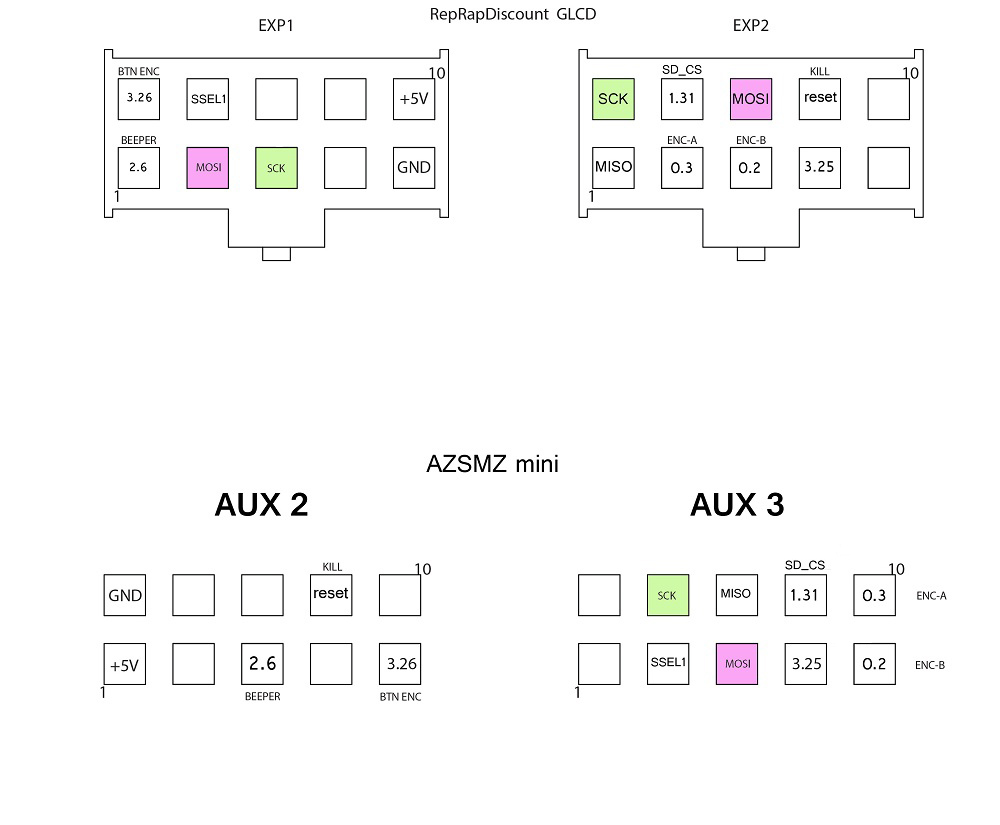
I have put some time into sorting out the pinouts of the connectors of the RepRapDiscount Full Graphic Smart Controller LCD panel.
This lcd panel is called 'reprap_discount_glcd' for the 'panel.lcd' option in the config.txt file.
I had one laying around and did not want to buy the AZSMZ mini lcd controller yet. The pint outs of the reprap_discount_glcd are not compatible with the AZSMZ mini board connectors, so you need to make the correct connections yourself.
To help others with the same task ahead, I have created a table to make the correct wire connections and assign the correct pins to the SmoothieWare firmware config.txt file.
The external SD card reader I have not tried to connect yet, the connections for this are thus missing in the pdf.
I have also read there are some issues with that specific combination (SPI channel conflict) and will use the internal micro SD card reader on the board for now.
The lines I have in my config.txt for this lcd panel, which work correct for me:
# Panel See [smoothieware.org]
panel.enable                                 true              # set to true to enable the panel code

# Example for reprap discount GLCD
# on glcd EXP1 is to left and EXP2 is to right, pin 1 is bottom left, pin 2 is top left etc.
# +5v is EXP1 pin 10, Gnd is EXP1 pin 9

panel.lcd                                   reprap_discount_glcd 	       #
panel.spi_channel                           0                 # OK spi channel to use  ; GLCD EXP1 Pins 3,5 (MOSI, SCLK)
panel.spi_cs_pin                            SSEL1             # OK spi chip select     ; GLCD EXP1 Pin 4
panel.encoder_a_pin                         1.27!^            # OK encoder pin         ; GLCD EXP2 Pin 3
panel.encoder_b_pin                         1.25!^            # OK encoder pin         ; GLCD EXP2 Pin 5
panel.click_button_pin                      3.26!^            # OK click button        ; GLCD EXP1 Pin 2
panel.buzz_pin                              1.30              # OK pin for buzzer      ; GLCD EXP1 Pin 1
#panel.button_pause_pin                      1.23!^            # kill/pause          ; GLCD EXP2 Pin 8 either
#panel.back_button_pin                       1.23!^            # back button         ; GLCD EXP2 Pin 8 or
kill_button_enable                          true              # OK set to true to enable a kill button
kill_button_pin                             1.23^             # OK kill button pin. default is same as pause button 2.12 (Add ^ for external buttons)

panel.contrast                               18               # OK override contrast setting (default is 18)
panel.encoder_resolution                     2                # OK override number of clicks to move 1 item (default is 2)
panel.menu_offset                            1                # OK here controls how sensitive the menu is. some panels will need 1

panel.alpha_jog_feedrate                     6000             # x jogging feedrate in mm/min
panel.beta_jog_feedrate                      6000             # y jogging feedrate in mm/min
panel.gamma_jog_feedrate                     3000             # z jogging feedrate in mm/min

panel.hotend_temperature                     242              # temp to set hotend when preheat is selected
panel.bed_temperature                        100              # temp to set bed when preheat is selected

# setup for external sd card on the RRD GLCD which shares the onboard sdcard SPI port
panel.external_sd                            false            # set to true if there is an extrernal sdcard on the panel
panel.external_sd.spi_channel                1                # set spi channel the sdcard is on
panel.external_sd.spi_cs_pin                 0.28             # set spi chip select for the sdcard (or any spare pin)
panel.external_sd.sdcd_pin                   0.27!^           # sd detect signal (set to nc if no sdcard detect) (or any spare pin)
|
Re: AZSMZ mini + LCD April 19, 2018 04:32PM |
Registered: 5 years ago Posts: 2 |
Hi all
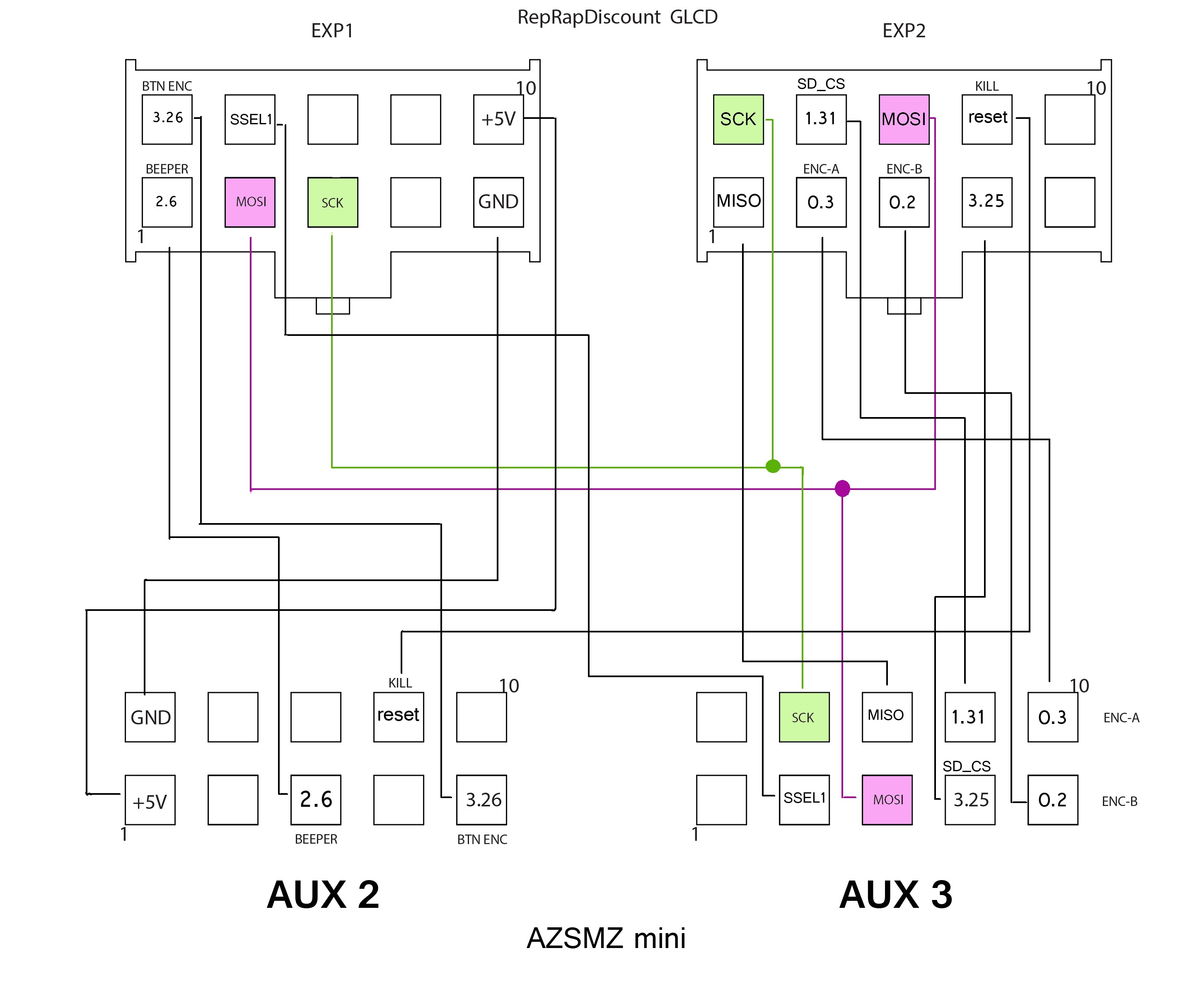
I've recently purchased AZSMZ mini and for some reason original display didn't work so i hooked up RRD GLCD.
Eventually it worked but was little bit tricky because i had to make my own cable.
Thanks to 3DFreezeMe for his connection table and config.
I`m adding my connection scheme. ( pay attention that same MOSI and SCK are connected to both EXT1 and EXT2)
Both LCD and external SD card are working
And my config is:
# LCD Panel
# ---------------------------------------------------------------------
panel.enable true # set to true to enable the panel code
panel.lcd reprap_discount_glcd
panel.spi_channel 0 # spi channel to use ; GLCD EXP1 Pins 3,5 (MOSI, SCLK)
panel.spi_cs_pin SSEL1 # spi chip select ; GLCD EXP1 Pin 4
panel.encoder_a_pin 0.3!^ # encoder pin ; GLCD EXP2 Pin 3
panel.encoder_b_pin 0.2!^ # encoder pin ; GLCD EXP2 Pin 5
panel.click_button_pin 3.26!^
panel.buzz_pin 2.6
# SD
#-------------------------------------------------------------------------
panel.external_sd true # set to true if there is an extrernal sdcard on the panel
panel.external_sd.spi_channel 0 # set spi channel the sdcard is on
panel.external_sd.spi_cs_pin 1.31 # set spi chip select for the sdcard
panel.external_sd.sdcd_pin 3.25!^ # sd detect signal (set to nc if no sdcard detect)
|
Re: AZSMZ mini + LCD April 24, 2018 03:16PM |
Registered: 8 years ago Posts: 29 |
many thanks for your connection diagram.
I have one question: do I have to connect SCK from aux 3 of the azsmz to both SCK pins in EXP 1 and EXP2 ?
I understand that I need to make this 1 to 2 pins connection also for MOSI, is that correct ?
right now the panel is working and recognize the SD card but cant get the files to be listed.
I have one question: do I have to connect SCK from aux 3 of the azsmz to both SCK pins in EXP 1 and EXP2 ?
I understand that I need to make this 1 to 2 pins connection also for MOSI, is that correct ?
right now the panel is working and recognize the SD card but cant get the files to be listed.
|
Re: AZSMZ mini + LCD April 25, 2018 03:00PM |
Registered: 5 years ago Posts: 2 |

Sorry, only registered users may post in this forum.