Engraving PC boards.
Posted by sheep
|
Engraving PC boards. February 11, 2010 04:51PM |
Registered: 15 years ago Posts: 132 |
My 20 year old Desktop CNC, which I expect to use as a repstrap, was intended for use as a PC-board engraving machine. A watchmaker friend/mentor bought it at auction, then got tired of it and sold it to me some 10 or so years ago. I was the only one that could make it work.
Engraving a PC board requires the opposite of the Gerber file. Gerber is a special case of G-code files, which are the same files used by many repraps. These files drive a photo-plotter and like the reprap are additive processes. One adds the enchant mask to the photo plot.
An engraved PC-board needs the copper removed. Over the last few years there has been an Eagle layout editor script, which makes the correct tool-paths[1]
For some years I have been reading the related e-group(Now a Yahoo company) I have also talked with manufactures at trade shows.
The best tip for engraving the board is a 60 degree angle, these can be ground from broken PC mills. Speed is also important. A dremmel could be used, although the bearings (runout) is a bit much, Some users will repack the dremmel bearings, to improve runout.
I have a number of watchmaker tools which use solid bearings. Usually oiled bronze. These are really precise and can take the high speeds used in turning sub millimeter watch parts. Such bearings are sold at hardware stores. They are porous and can be cooled with oil cups. A simple belt drive and hobby motor can be used to turn a cutter at high RPM, using a belt pulley system. Older watchmaking tools used bearings of babbit, which is effectively solder. This melts slightly under the friction from rotation and has been used for centuries.
The circuit board is held to the table by turners tape, which is what woodworkers use to attach bowls to the head of a lathe.
The trick when engraving is to use a contact router ring, made from something like a Teflon(I think is what the heater barrel is usually made from this material.) The weight of the router head keeps the PC flat and the engraving tip a fixed distance from the work. In effect the head floats over the PC board. Provisions are needed to raise this engraving head and a vacuum system used to remove the dust.
Ironically it was the dust, that 20 years ago caused my machine to be surplussed. The dust was as bad as the enchant chemicals when breathed.
Since the engraving conversion script is already in existence for Eagle, why is there not more being done, to create a routing head for Mendel and toolpaths saved in the distribution builds?
-julie
[1] isolation routing
|
Re: Engraving PC boards. February 11, 2010 05:35PM |
Registered: 16 years ago Posts: 1,094 |
My understanding is that mendel's mechanical construction isn't designed to be strong enough to take the force of routing/milling without unacceptable levels of deformation. If it's only doing light loads and you can work out how to actually fit the motor under the gantry, feel free to tell us what it can and can't do.
-----------------------------------------------
Wooden Mendel
Teacup Firmware
-----------------------------------------------
Wooden Mendel
Teacup Firmware
|
Re: Engraving PC boards. February 11, 2010 06:44PM |
Admin Registered: 17 years ago Posts: 7,879 |
Thanks for the info Julie, I have been thinking about a decent PCB milling spindle recently.
So are ball bearings not good enough for a PCB milling spindle?
I have a watchmakers lathe that is small enough that I could mount the headstock and spindle on my z-axis. I don't know if I fancy running it at 50K RPM or similar though as lathes normally run much slower.
I was thinking of using a model aircraft motor with a belt or a rubber coupler.
The two big problems with PCB milling I see are the price and wear rate of the cutters and the fact that most boards I do these days need thermal vias under the chips. I know electrical vias can be made with a stencil, paste and bake method but I don't know if they are good thermal conductors.
[www.hydraraptor.blogspot.com]
|
Re: Engraving PC boards. February 11, 2010 07:46PM |
Registered: 15 years ago Posts: 132 |
PC board engraving, only needs to take the lightest of cuts through the copper. AIRC about 30 or 40 microns.
The trick why I think Mendle can do it is based on the pro machine I saw at a tradeshow. Most engravers depend on the Z axis and a flat PC board. By floating the head over the board the depth of the cut is fixed, just like when using a trim router. All the XY axis has to to is to move the floating head. The Z would just need to lift it for the moves.
I think a watch lathe spindle would be too heavy for Mendel. It is more of the technology, that could be adapted. I am also thinking of something that can be replicated. As I noted, Babbit has been used for 100s of years as a bearing material.
The right ball races would work, These are after all what is inside of the dremel tool. I do not know enough about the specs as to what one would need for the speed needed on these bearings.
As for cost of cutters. There is a guy online, Paul Jones, who grinds the cutters from the old pc carbide bits. Granted this might involve a diamond hone. The website, while seeming a bit dated is entertaining and has some useful information on it.
Plated Vias are an issue, I looked into self plating and the "ink" is about 50USD a bottle, which makes sending boards out more attractive. Where the engraving comes in handy is for 1 off prototypes.
No experience with thermal vias. Is this how the SMD stepper chips heatsink? Could one just drill a hole and attach a heat-sink underneath that could bolt onto the board. I have seen things like this on some of the laptops, which I have taken apart.
I have been using smt for over 10 years. Recently I had to rework a through hole board. One had to clip the leads off the components and remove the pins one by one. I did use a heat gun, although this melted some of the connectors. Either way one had to use wick and a PC drill by hand to clear the holes. With SMT one just masks off the area with aluminum foil, hole a thermocouple up to the chip and hit the board with a heat gun. Often the chip can be used again.
-julie
|
Re: Engraving PC boards. February 12, 2010 12:20PM |
Admin Registered: 17 years ago Posts: 1,791 |
It's not so much "not invented here" or "if it is subtractive it is not RepRap" as "No one's gotten around to it yet".
I'll showcase it on the blog once someone figures this out.
[objects.reprap.org]
I'll showcase it on the blog once someone figures this out.
[objects.reprap.org]
|
Re: Engraving PC boards. February 12, 2010 03:27PM |
Admin Registered: 16 years ago Posts: 13,891 |
... in past i etched my PCB's single- and double-sided and inserted thin silvercoated copper-tubes (from 0.6mm to 1.2mm in diameter) in the via-bores, soldered the top-side, then inserted evantual components (if the via was a component-pin too) and soldered the bottom.
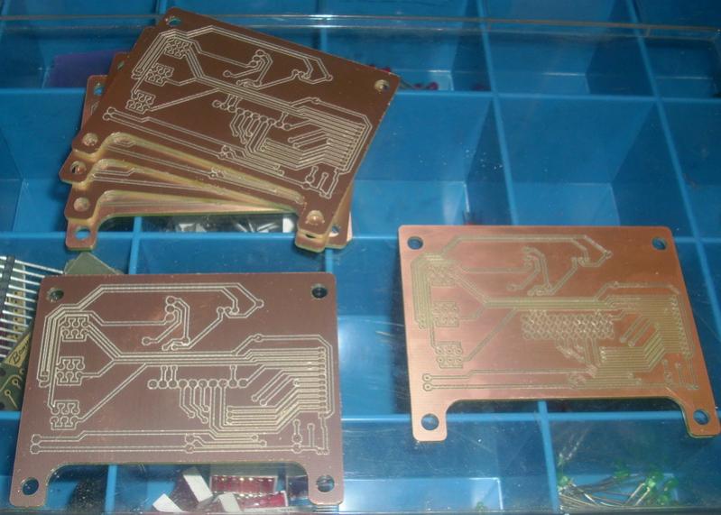
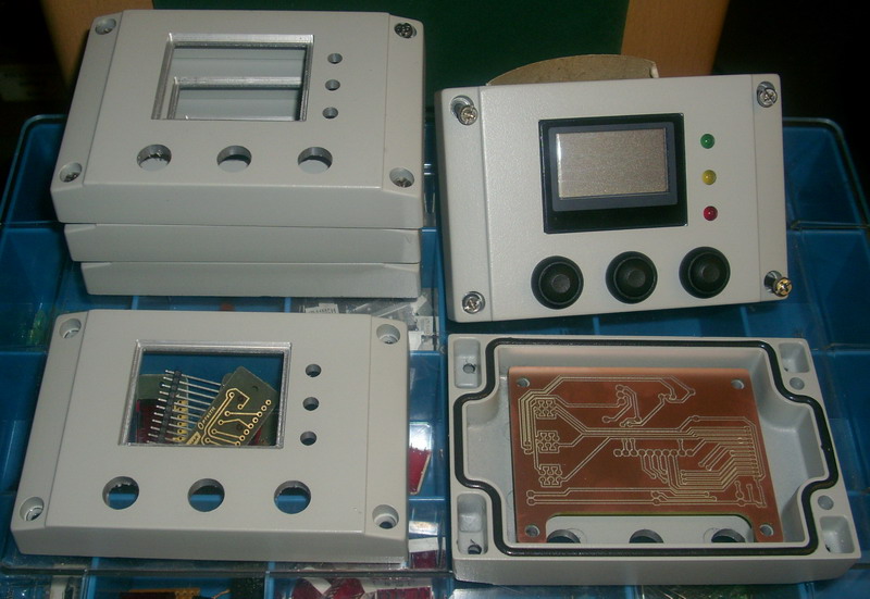
Actually i mostly mill my PCB's as outlines with 30°-millbits what's no problem for doublesided, complex contours or populated with SMT's.
Atached are images of some milled PCB and housings i made for a sensor-panel in small counts ...
Viktor
Actually i mostly mill my PCB's as outlines with 30°-millbits what's no problem for doublesided, complex contours or populated with SMT's.
Atached are images of some milled PCB and housings i made for a sensor-panel in small counts ...
Viktor
Sorry, only registered users may post in this forum.