About Pin Number Question?
Posted by Sola
|
About Pin Number Question? May 14, 2014 08:56AM |
Registered: 9 years ago Posts: 3 |
Hello I'm new here. Help me ~~ thanks
At first, I had arduino Mega 2560 board and big easy driver and a stepper motor.
Follow this article,(http://www.schmalzhaus.com/EasyDriver/Examples/EasyDriverExamples.html)
I can make my motor moving with Arduino IDE successfully.
Next, I want to use creation workshop software to control my motor.
But, I found I need upload the firmware, sprinter and marlin, into my arduino mega board, I did it.
But But But...I have no ramps board.
Thus, I try to find how to connect between Arduino Mega and big easy driver (find correct pin number) directly.
Actually, I don't know how to connect two without Ramps.
I look for pin numbers as follows as from (http://reprap.org/wiki/RAMPS_1.4)
and check where these pin numbers are from ( [arduino.cc] )
#define Z_STEP_PIN 46
#define Z_DIR_PIN 48
#define Z_ENABLE_PIN 62
#define Z_MIN_PIN 18
#define Z_MAX_PIN 19
big easy driver board has three pins, step, direction and Ground.
but these #define stuff has five pins above. @@
Could someone tell me how to connect correctly?? or I have to buy ramps board.
Thanks a lot. @@ ~~
Edited 1 time(s). Last edit at 05/14/2014 08:57AM by Sola.
|
Re: About Pin Number Question? May 14, 2014 02:44PM |
Registered: 13 years ago Posts: 1,352 |
#define Z_MIN_PIN 18
#define Z_MAX_PIN 19
These are endstops pins. Normally only a MIN is used, one per axis. The mechanical endstop configuration is with internal pullups enabled on that pin, and the mechanical pullup is used as "normally connected" hence it always puts the internal pullup current to ground. So to trick the firmware in thinking you have a endstop there, just put a jumper on it, or otherwise short that pin to ground. For testing purposes and such. In case the endstop gets hit, it disconnects, and the internal pullup raises the line to 5v, and the uC reads 5V on that pin immediatelly.
The MAX pin is typically not used (set as -1), because after homing the firmware knows its limits, so it sort of uses software endstops. Meaning if your Z axis is set for 100mm high in config, and you home it and then order it a 101mm move, it will only move 100mm because it will not move above that "software" limit which is set by the configured length of that axis. Also to note, you can use only one pin for all 3 endstops, connected in series, with the condition that firmware is set in such a way that after hitting an endstop, it retracts from it 2-3 mm away, such that endstop is back in continuity again. But thats not typical.
Mechanical endstops have 3 pins, from which two of them are as NC "normally connected", meaning they are conducting when endstop is not pressed, and they disconnect when endstop is pressed. You can measure this with a multimeter. These two pins, one goes to gnd, and one goes to the gpio pin defined as MIN in pins.h. You also need to enable internal pullup on that pin in firmware. If not enabled in firmware, then you need a phisical pullup, that is 10k resistor from that pin to 5v line. Thats all, cheers.
Edited 1 time(s). Last edit at 05/14/2014 03:22PM by NoobMan.
|
Re: About Pin Number Question? May 16, 2014 12:13AM |
Registered: 9 years ago Posts: 3 |
Thanks very much for your explanation in detail.
I can control my stepper motor now by using Creation Workshop software with Sprinter firmware.
Until yesterday night, I did't figured out these pin number where they are.
For example, PIN 46 means digital pin 46 (PWM) in Arduino Pin Mapping. (http://arduino.cc/en/uploads/Hacking/PinMap2560big.png)
Actually, I thought PIN 46 means PD3(TXD1/INT3) before, because it shows the 46 number on map. @@ it's wrong.
It has another main reason why I don't find correct pins that PIN 62 which I can't find where it is in map, thus I got into a mess.
Finally, I had known PIN 62 means Analog PIN 8 (A8).The calculation is just to accumulate the number from digital pin to analog pin.
PIN 62 = 53 (Digital PIN) + 9 (Analog PIN 0~8) = Analog PIN 8
It seems everyone understands this? XDD ~~|||
#define Z_STEP_PIN 46
#define Z_DIR_PIN 48
#define Z_ENABLE_PIN 62
#define Z_MIN_PIN 18
#define Z_MAX_PIN 19
I connected PIN 46(Step), PIN 48(Dir) into my Arduino board mega successfully
and try to make the end stop function works(PIN 18(MIN) connect to ground or not).
Having another problem now about ENABLE PIN.
I connected ENABLE PIN 62 (Analog PIN 8) into Enable port on the easy big driver board(EBD).
But I press enable or disable button on the Creation Workshop Software, it didn't work.
Could it be firmware problem I need to change definition? or I can't connect PIN 62 to Enable Port on EBD directly?
Besides, MS1 MS2 M3 PIN which I need to try to figure out how to make them work on EBD.
Thanks a lot your help!!!
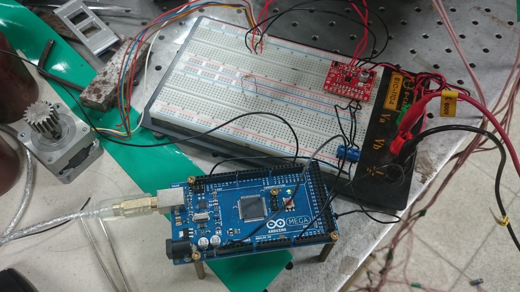
Attached file is my first time to control machines ^^ ~~
Next, I wanna control my stepper motor with optical encoder where I found it in old platform machines. Orz...
Edited 2 time(s). Last edit at 05/16/2014 12:15AM by Sola.
I can control my stepper motor now by using Creation Workshop software with Sprinter firmware.
Until yesterday night, I did't figured out these pin number where they are.
For example, PIN 46 means digital pin 46 (PWM) in Arduino Pin Mapping. (http://arduino.cc/en/uploads/Hacking/PinMap2560big.png)
Actually, I thought PIN 46 means PD3(TXD1/INT3) before, because it shows the 46 number on map. @@ it's wrong.
It has another main reason why I don't find correct pins that PIN 62 which I can't find where it is in map, thus I got into a mess.
Finally, I had known PIN 62 means Analog PIN 8 (A8).The calculation is just to accumulate the number from digital pin to analog pin.
PIN 62 = 53 (Digital PIN) + 9 (Analog PIN 0~8) = Analog PIN 8
It seems everyone understands this? XDD ~~|||
#define Z_STEP_PIN 46
#define Z_DIR_PIN 48
#define Z_ENABLE_PIN 62
#define Z_MIN_PIN 18
#define Z_MAX_PIN 19
I connected PIN 46(Step), PIN 48(Dir) into my Arduino board mega successfully
and try to make the end stop function works(PIN 18(MIN) connect to ground or not).
Having another problem now about ENABLE PIN.
I connected ENABLE PIN 62 (Analog PIN 8) into Enable port on the easy big driver board(EBD).
But I press enable or disable button on the Creation Workshop Software, it didn't work.
Could it be firmware problem I need to change definition? or I can't connect PIN 62 to Enable Port on EBD directly?
Besides, MS1 MS2 M3 PIN which I need to try to figure out how to make them work on EBD.
Thanks a lot your help!!!
Attached file is my first time to control machines ^^ ~~
Next, I wanna control my stepper motor with optical encoder where I found it in old platform machines. Orz...
Edited 2 time(s). Last edit at 05/16/2014 12:15AM by Sola.
|
Re: About Pin Number Question? May 16, 2014 08:13AM |
Registered: 13 years ago Posts: 1,352 |
If you do not actually use a ramps board, it is better to avoid that for motherboard setting. Ramps had several versions which resulted in a confusing and stacking pin definition and nested #if conditions.
In configuration.h, use MOTHERBOARD=99 and then go in pins.h and find this motherboard=99 and work with that pin definition instead. I find it better. I took what i used for pins, and i changed endstops MIN to -1 so you do not get in faults with them. Replace the #if motherboard 99 condition with the following:
The pins locations are based on convenience, you could change pins almost anywhere else. Only the thermistor pins have to be on an analog pin (A0-A15).
The firmware has some checks in many places, for example if when an endstop is triggered. In your previous post i think you had both min and max endstops defined, and not shorted to ground, so both were basically triggered. I dont know what firmware does in that situation with both endstops triggered but its understandable that problems would occur. If a min endstop is triggered, the firmware will ignore commands to move it below that point and will move only to one direction opposite of the min endstop. If you have both min and max endstop triggered, thats a corner case in which who knows exactly what happens, perhaps the situation was not anticipated by programers, but anyway its understandable why it did not worked.
Also if you want to change dir/stp/en you can also test Z, X or Y axes, but probably not E. Probably you will get errors at extruder and that is to be expected because in defaults in configuration.h there is set to check the extruder temperature before extruding (you can set that to avoid this check).
You can also hack into the babystep function to fix 2 buttons, one to move the Z axis up and the other to move Z down. That is instead of using an encoder. But there are differences between these two setups. With encoder, it will make a move proportional to the angle of encoder rotation. With buttons it will simply move as long as you keep the button pressed, which also could be dangerous if it gets stuck or otherwise shorted.
Edited 2 time(s). Last edit at 05/16/2014 08:34AM by NoobMan.
In configuration.h, use MOTHERBOARD=99 and then go in pins.h and find this motherboard=99 and work with that pin definition instead. I find it better. I took what i used for pins, and i changed endstops MIN to -1 so you do not get in faults with them. Replace the #if motherboard 99 condition with the following:
#if MOTHERBOARD == 99

#ifndef __AVR_ATmega1280__
 #ifndef __AVR_ATmega2560__
 #error Oops!  Make sure you have 'Arduino Mega' selected from the 'Tools -> Boards' menu.
 #endif
#endif

#define KNOWN_BOARD 1
//#define LARGE_FLASH true

#define Z_DIR_PIN            22
#define Z_ENABLE_PIN   24
#define Z_STEP_PIN         26
#define Z_MIN_PIN           -1 //all min/max endstops disabled with -1 to avoid faults on them
#define Z_MAX_PIN         -1

#define X_DIR_PIN             23
#define X_STEP_PIN         25
#define X_ENABLE_PIN    27
#define X_MIN_PIN          -1
#define X_MAX_PIN        -1

#define Y_DIR_PIN             28
#define Y_STEP_PIN         30
#define Y_ENABLE_PIN   32
#define Y_MIN_PIN          -1
#define Y_MAX_PIN        -1

#define E0_DIR_PIN            29
#define E0_STEP_PIN         31
#define E0_ENABLE_PIN    33

//#define E1_DIR_PIN          34 //not used
//#define E1_STEP_PIN         36
//#define E1_ENABLE_PIN       38

#define LED_PIN            -1 //13
#define PS_ON_PIN          -1
#define KILL_PIN           -1

#define HEATER_0_PIN        7   //extruder
#define HEATER_1_PIN       -1   //extruder fan
#define HEATER_2_PIN       -1
#define HEATER_BED_PIN      4
#define FAN_PIN             5

#define TEMP_0_PIN          1   // MUST USE ANALOG INPUT NUMBERING NOT DIGITAL OUTPUT NUMBERING!!!!!!!!!
#define TEMP_1_PIN          2   // MUST USE ANALOG INPUT NUMBERING NOT DIGITAL OUTPUT NUMBERING!!!!!!!!!
#define TEMP_2_PIN         -1   // MUST USE ANALOG INPUT NUMBERING NOT DIGITAL OUTPUT NUMBERING!!!!!!!!!
#define TEMP_BED_PIN        3

#define SDPOWER          -1
#define SDSS             53
#define MISO_PIN         50
#define MOSI_PIN         51
#define SCK_PIN          52

#define BEEPER -1

#endif /* 99 */
The pins locations are based on convenience, you could change pins almost anywhere else. Only the thermistor pins have to be on an analog pin (A0-A15).
The firmware has some checks in many places, for example if when an endstop is triggered. In your previous post i think you had both min and max endstops defined, and not shorted to ground, so both were basically triggered. I dont know what firmware does in that situation with both endstops triggered but its understandable that problems would occur. If a min endstop is triggered, the firmware will ignore commands to move it below that point and will move only to one direction opposite of the min endstop. If you have both min and max endstop triggered, thats a corner case in which who knows exactly what happens, perhaps the situation was not anticipated by programers, but anyway its understandable why it did not worked.
Also if you want to change dir/stp/en you can also test Z, X or Y axes, but probably not E. Probably you will get errors at extruder and that is to be expected because in defaults in configuration.h there is set to check the extruder temperature before extruding (you can set that to avoid this check).
You can also hack into the babystep function to fix 2 buttons, one to move the Z axis up and the other to move Z down. That is instead of using an encoder. But there are differences between these two setups. With encoder, it will make a move proportional to the angle of encoder rotation. With buttons it will simply move as long as you keep the button pressed, which also could be dangerous if it gets stuck or otherwise shorted.
Edited 2 time(s). Last edit at 05/16/2014 08:34AM by NoobMan.
Sorry, only registered users may post in this forum.