TB6560 driver board
Posted by Petrus
|
TB6560 driver board July 04, 2012 12:00PM |
Registered: 12 years ago Posts: 162 |
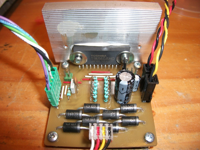
To improve the performances of my heavy Mendel [forums.reprap.org] I need powerful steppers drivers, so I designed a driver board based on the TB6560AHQ driver circuit :
Instead of expensive and hard to find power resistors, I use several 1ohm small resistors in parallel, each resistor adds 500mA to the driving current.
Current, excitation mode and decay mode can be adjusted using jumpers.
The circuit is single sized and can be mechanically engraved :
The kicad project files and .pdf files are available on the wiki : [reprap.org]

Instead of expensive and hard to find power resistors, I use several 1ohm small resistors in parallel, each resistor adds 500mA to the driving current.
Current, excitation mode and decay mode can be adjusted using jumpers.
The circuit is single sized and can be mechanically engraved :

The kicad project files and .pdf files are available on the wiki : [reprap.org]
|
Re: TB6560 driver board July 05, 2012 04:57AM |
Registered: 13 years ago Posts: 7,616 |
|
Re: TB6560 driver board July 05, 2012 10:20PM |
Registered: 13 years ago Posts: 632 |
|
Re: TB6560 driver board July 06, 2012 11:53AM |
Registered: 12 years ago Posts: 162 |
I did not see the AKA47 design before. The schematic is the same, except for additional pull-down resistors I put just in case and the reset RC circuit.
What I don't like in this design as well as other design I found is that there are components on the rear of the TB6560 so you can't put a thick heat sink on it.
The one I put on the prototype would fit on AKA47 design too, but it get very hot at maximum current, I will need bigger ones for X and Y axis.
|
Re: TB6560 driver board July 08, 2012 07:15AM |
Registered: 13 years ago Posts: 1,352 |
How did u do the Vmotor voltage delay for the proper "start up sequence"? Curious to compare variants. I seen several transistors and high side fets solutions, but i considered them too dependant on the Vm voltage itself, which i want to keep it variable to play with, so i just had to put a relay instead.
|
Re: TB6560 driver board July 08, 2012 10:31AM |
Registered: 12 years ago Posts: 162 |
The Vmot delay and soft start will be handled by a dedicated circuit, I already put the schematic on an other thread :
/!\ wrong schematic/![/b]
It still needs to be tested.
The problem with a relay is the current surge due to the capacitors, I don't think a relay will last very long without a soft start circuit.
Edited 1 time(s). Last edit at 07/09/2012 12:28PM by Petrus.
/!\ wrong schematic/![/b]

It still needs to be tested.
The problem with a relay is the current surge due to the capacitors, I don't think a relay will last very long without a soft start circuit.
Edited 1 time(s). Last edit at 07/09/2012 12:28PM by Petrus.
|
Re: TB6560 driver board July 08, 2012 02:36PM |
Registered: 13 years ago Posts: 1,352 |
Tb6560 "usage recomandations" datasheet gives caps range 10-100uF electrolitic + 0.1-1uF ceramic, both for Vmot and 5v (strangely coz 5v makes sense to have lower). I'd say 47uF+0.47 would be somewhat in middle and what would make some sense. I dont think using larger caps would have a positive effect, on the contratily can give problems like that. Tb6560 is known not to have issues with noise, but just to blow up plain and simply, from what i read around most blowup seems to be related to reset line or i would guess power on transients on Vm (last one with larger caps dont know how that can help). I dont know where is the 470uF value coming from, but if it was from a reliable source please let me know more of it.
From what i guess, further more caps value may be linked to switching frecv, therefore need to look at Cosc, which gives the Fosc, so to me it means something like when Fosc is lower then the higher range cap makes sense, and when Fosc is higher frecv, then it can use lower caps. At least from a switching perspective that makes sense to me, e.g. increasing switching frecv allows (or leads to) using smaller caps. So from what i can gather the default recomendation of caps being set for something like Cosc=330pF (~129khz) but like lower values seem to work much better: Cosc 100pF=400khz or 220pF=191kHz, then bottomline probably another reason to give caps some cuts even from that.
From what i guess, further more caps value may be linked to switching frecv, therefore need to look at Cosc, which gives the Fosc, so to me it means something like when Fosc is lower then the higher range cap makes sense, and when Fosc is higher frecv, then it can use lower caps. At least from a switching perspective that makes sense to me, e.g. increasing switching frecv allows (or leads to) using smaller caps. So from what i can gather the default recomendation of caps being set for something like Cosc=330pF (~129khz) but like lower values seem to work much better: Cosc 100pF=400khz or 220pF=191kHz, then bottomline probably another reason to give caps some cuts even from that.
|
Re: TB6560 driver board July 09, 2012 12:27PM |
Registered: 12 years ago Posts: 162 |
The 470uF was just a guess but actually it is justified, the example on the datasheet show a 47uF capacitor on Vmot with an Fosc of 400kHz, with a current set at 1A/phase.
With Cosc = 470pF I get a switching frequency around 30kHz (measured with an oscilloscope) and I will use the driver at 3A/phase.
Big capacitors can also absorb more energy from back EMF during direction changes, and I will have quite a big mass to move at high speed (heated glass bed on the Y axis and a dual extruder on the X axis, my goal is to print at 100mm/s)
I can increase the frequency but I am a bit worried about the additional heat that may be generated.
I need to get a thermocouple thermometer and do some additional tests.
And by the way my soft start schematic is wrong, it will apply a Vgs of 24V which can damage the mosfet, here is the corrected one :

|
Re: TB6560 driver board July 09, 2012 04:38PM |
Registered: 13 years ago Posts: 1,352 |
Capacitor Oscillating // Frequency // Minimum Clock Pulse Width tW(CLK) (Note 1)
1000 pF // 44 kHz // 90 μs (Note 2)
330 pF // 130 kHz // 30 μs
100 pF // 400 kHz // 10 μs (Note 2)
Note 1: When the frequency of an input clock signal is high, the COSC value should be small so that the duty cycle
of an input clock pulse does not become extremely high (should be around 50% or lower).\
Note 2: Not tested in production.
So default is 330pF - 130 kHz - 30uS. With Cosc of 470pF i calculate you get an approximate of 91.67 kHz, not 30. To actually get 30kHz u need Cosc of ~1470, that is 1000pF more. You can also see from the table, to get 30kHz u need to be well over 1000pF. At least by their formula approximation. The actual formula in datasheet is wrong, has a typo: the last operation is written as + but is in fact x. But other than that the formula seem to work. And it just occured to me that theoretical value might differ, in practice could depend on which points u measure, what microstep it is, what speed of the movement, etc. Try changing something like that microstep or issue faster moves and see how it turns out.
From the default 330pF what i meant was that is desirable to go lower Cosc: 220 or 100 even. Lower Cosc gives higher switching thus makes that "minimum clock pulse width" smaller, which i think is better. Per note 1 could compare it with our step signal max rate from firmwares, but i personally didnt bothered as i think 100-220pF is better anyway. Things should run smoother like that (than otherwise). Allowing lower caps is just a minimal side effect that can be ignored. But running should feel smoother with 100 or 220 and well above the audible range, whereas at 30kHz (and top with 50% "or lower" input clock width) should be quite noisy. Try yourself different values and see how it works with your motors but my money is on faster switch is better. If you do try, with certain motors i think you should feel quite a difference between 1000pF and 100pF Cosc.
This is how i see it. Maybe i am mistaking somewhere, if so pls dont hesitate to point out. I typically make so many mistakes everyday that i amaze myself. The only difference is that on a good day mistakes are funny, and on the other day they arent
Bottomline I wouldnt use 470uF myself, feels overkill, in general I quite love a good overkill (love the sink + SR diodes), but the caps one has probably no benefit except it might just make higher surge current / transient current at power on. That shouldnt normally be significant, but in this case it just might, as this ic is well known to blow up at powerup just like that. I'd rather use 47uF at entry and Cosc either 100 or 220 max, but again thats just me.
On the overall doesnt really matter, you got a nice driver there, congratulations for it.
Edited 1 time(s). Last edit at 07/09/2012 05:02PM by NoobMan.
|
Re: TB6560 driver board July 09, 2012 05:12PM |
Registered: 12 years ago Posts: 162 |
I was also surprised by the low switching frequency, at first I put a 1nF capacitor and it was very noisy, then I changed it to a 470pF, the switching frequency is now above the human ear range, I will try lower values and check it it heats-up more.
On the Electrical Characteristics table on the last line you can see that the frequency can vary from 60 to 200kHz with the standard 330pF capacitor, the oscillator is not precise.
On the Electrical Characteristics table on the last line you can see that the frequency can vary from 60 to 200kHz with the standard 330pF capacitor, the oscillator is not precise.
|
Re: TB6560 driver board July 09, 2012 06:51PM |
Registered: 13 years ago Posts: 1,352 |
Indeed thats quite some 300%+ margin i didnt took into account.
Yes that difference in stepper behaviour exactly what i was talking about, glad you could sense it, i would of rested two posts ago if i knew that too.
Gratz again for the driver and may it work best, serve you 100 years and never blow up
Yes that difference in stepper behaviour exactly what i was talking about, glad you could sense it, i would of rested two posts ago if i knew that too.
Gratz again for the driver and may it work best, serve you 100 years and never blow up
|
Re: TB6560 driver board July 15, 2012 02:11PM |
Registered: 14 years ago Posts: 800 |
looking at this board i could not help but to think if a person could not modify it to fit into the pololu board slot like a riser card. that way you could fit them onto a ramps board and it could be very easy to cool
[mike-mack.blogspot.com]
[mike-mack.blogspot.com]
|
Re: TB6560 driver board July 15, 2012 06:40PM |
Registered: 13 years ago Posts: 1,352 |
For reprap use the sense resistors need to be set for like 0.6-0.8-1A which i think its usual nema17 reprap motors, and probably sr diodes need to be taken off, also alot of settings like microstep etc can be hardwired.
With support components reduced to a minimal maybe its possible to get a small driver footprint like that to fit in a ramps shield.
But at a current under 1A these drivers dont break a sweat, dont get any heat and therefore shouldnt need any kind of cooling, probably not even passive radiator or anything.
|
Re: TB6560 driver board March 28, 2013 10:05AM |
Registered: 11 years ago Posts: 1 |
|
Re: TB6560 driver board March 29, 2013 07:19PM |
Registered: 12 years ago Posts: 162 |
|
Re: TB6560 driver board March 30, 2013 12:28PM |
Registered: 11 years ago Posts: 369 |
fwoooo this is very interesting for me ... wad a nice machine !!!
and the belt doubler idea is very nice
[www.youtube.com]
was he trying to play a song from the motor noise?
with that, it also almost effectively doubles the amount of torque of a smaller motor !!! vive la NEMA 17 !!!
Edited 2 time(s). Last edit at 03/30/2013 12:33PM by redreprap.
______________________________________
__my mixed bag blog || aka --> [http] || ___ so 3D printing is everywhere ... dont worry, hospitals can now 3Dprint body parts, they will charge you $1million excluding surgical fees ... you will die paying your debts. thats their aim ___ if every patent expires tomorrow, everybody will surely get a 3dprinter and make EVERYTHING ! ____ there is a "DIY-DTG" t shirt printing forum, you can mod an EPSON printer to PRINT like a pro. ___ CNCzone? overly commercialized it seems ___ my country? they will be taxing you for every cm of road you use and track you to your grave using GPS and its government authorized, now they will fire all the traffic wardens instead.___ EEVBLOG? there is only 1 way to do things --> take it apart like a pro
|
Re: TB6560 driver board March 31, 2013 12:18AM |
Admin Registered: 11 years ago Posts: 1,063 |
i have a modiciation for marlin if you have problems with missing steps due to the very short step pulses,
-=( blog )=- -=( thingiverse )=- -=( 3Dindustries )=- -=( Aluhotend - mostly metal hotend)=--=( Facebook )=-
|
Re: TB6560 driver board May 05, 2013 10:35AM |
Registered: 10 years ago Posts: 209 |
Hi.
Very nice TB board.
I'm using same drivers for my Printrboard and Gen 7 TM.
Wondering how critical the caps on 12 V and 5 V line are for TB and how sensible TB is to noises.
I have some crazy noises on my steppers and thought maybe you can help me.
I will post some photos and some more if you are interested.
|
Re: TB6560 driver board May 05, 2013 03:54PM |
Registered: 12 years ago Posts: 162 |
|
Re: TB6560 driver board May 29, 2013 05:13PM |
Registered: 13 years ago Posts: 632 |
Sorry, only registered users may post in this forum.