Problème de connexion moteur
Posted by JeremyFala
|
Problème de connexion moteur April 16, 2015 04:46PM |
Registered: 9 years ago Posts: 12 |
Bonjour à tous,
Je me présente rapidement, Jérémy 25 ans, ingénieur en mécanique et je travail en production.
Je me lance depuis quelques semaines dans la construction d'une prusa I3 et maintenant que tout est cablé j'ai un problème....
Mon lit chauffe, mon extrudeur aussi mais aucun moteur ne bouge !
J'ai vérifié et re vérifié mes branchements, ça à l'air de coller. J'ai plus l'impression qu'aucune tension ne sort de ma ramps 1.4
Alors question ! Etant donné que j'ai que 3 sur 4 polulu de branché (mon 4ème a cramé...) est-ce normal que rien ne bouge ?
Si oui vers quoi dois m'orienté ? je deviens dingue en bricolant mon marlin de tous les cotés !
Merci d'avance
Jérémy
Edited 1 time(s). Last edit at 04/17/2015 02:12PM by JeremyFala.
|
Re: Problème de connection moteur April 16, 2015 04:54PM |
Registered: 9 years ago Posts: 107 |
Salut jef (diminutif)
je te rassures j'avais un soucis avec le paramétrage d'un de mes moteurs en l'occurrence l'entrainement du filament
et pour savoir s'il avait un problème j'ai inversé un cablage dessus, et fait un test manu avec repetier et ça fonctionnait
par la suite je l'ai activé
ce qui peut t'empêcher par exemple le filament de sortir c'est le témoin de chauffe de l'extruder "cold "
juste ça si non je suis pas sûre à 99%
si ne serais-ce une particularité d'une programmation (mais j'en doute...)
@+
|
Re: Problème de connection moteur April 16, 2015 05:43PM |
Registered: 10 years ago Posts: 2,014 |
|
Re: Problème de connection moteur April 16, 2015 07:53PM |
Registered: 9 years ago Posts: 107 |
je n'ai pas regardé sur ma carte mais c'est intéressant
InstructionsChaque module Pololu dispose d'un potentiomètre de réglage situé à côté du radiateur. Ce potentiomètre contrôle l'intensité du courant délivré à chaque moteur. Le fait de tourner le potentiomètre dans le sens anti-horaire (inverse des aiguilles d'un montre) reduit le courant envoyé au moteur. Le tourner dans le sens horaire augmente le courant délivré.
Commnencez par diminuer le courant jusqu'a ce que le moteur commence à vibrer sur place au lieu de tourner normalement. puis tourner le potentiomètre dans le sens des aiguilles d'une montre, 1/8ème de tour par 1/8ème de tours jusqu'a ce que le moteur commence à tourner. Tourner enfin le potentiomètre d'1/8ème de tour supplémentaire pour finaliser le réglage
Edited 3 time(s). Last edit at 04/16/2015 08:00PM by mks_1.2_i3.
|
Re: Problème de connection moteur April 17, 2015 04:31AM |
Registered: 10 years ago Posts: 482 |
Quote
JeremyFala
Bonjour à tous,
Je me présente rapidement, Jérémy 25 ans, ingénieur en mécanique et je travail en production.
Je me lance depuis quelques semaines dans la construction d'une prusa I3 et maintenant que tout est cablé j'ai un problème....
Mon lit chauffe, mon extrudeur aussi mais aucun moteur ne bouge !
J'ai vérifié et re vérifié mes branchements, ça à l'air de coller. J'ai plus l'impression qu'aucune tension ne sort de ma ramps 1.4
Alors question ! Etant donné que j'ai que 3 sur 4 polulu de branché (mon 4ème a cramé...) est-ce normal que rien ne bouge ?
Si oui vers quoi dois m'orienté ? je deviens dingue en bricolant mon marlin de tous les cotés !
Merci d'avance
Jérémy
Un truc tout bête mais qui peut vite s'oublier, as-tu mis les jumpers sous les pololu ? (3 jumpers sous chacun)
- Prusa I3 rework HomeMade
- Roxanne HomeMade
- Prusa I2 Kit (à légué sa place à roxanne)
- iTopie En cours (Conception par Skarab)
Sur tout ça un extrudeur WadeL3K : [www.thingiverse.com]
|
Re: Problème de connection moteur April 17, 2015 05:03AM |
Registered: 9 years ago Posts: 107 |
salut pierrelesek
question bête c'est quoi le pololu
j'arrête pas de voir ce therme mais je ne vois pas trop
sur ma carte qui ressemble à celle-ci
c'est un accéléromètre c'est ça ?
question bête
c'est quoi le pololuj'arrête pas de voir ce therme mais je ne vois pas trop
sur ma carte qui ressemble à celle-ci

c'est un accéléromètre c'est ça ?
|
Re: Problème de connection moteur April 17, 2015 05:07AM |
Registered: 9 years ago Posts: 107 |

|
Re: Problème de connection moteur April 17, 2015 05:24AM |
Registered: 10 years ago Posts: 482 |
Salut,
Donc tu n'as pas une Ramps 1.4 et donc pas de cavaliers à installer la
Je ne sais pas d'où ça peut venir du coup là.
un pololu est une marque d'électronique et par abus de langage dans les reprap un pololu est le driver du moteur, ce qui envoi le signal et la puissance au moteur.
- Prusa I3 rework HomeMade
- Roxanne HomeMade
- Prusa I2 Kit (à légué sa place à roxanne)
- iTopie En cours (Conception par Skarab)
Sur tout ça un extrudeur WadeL3K : [www.thingiverse.com]
|
Re: Problème de connection moteur April 17, 2015 05:31AM |
Registered: 9 years ago Posts: 107 |

|
Re: Problème de connection moteur April 17, 2015 05:33AM |
Registered: 10 years ago Posts: 482 |
De la façon où t'as répondu j'ai cru que Jeremyfala et toi étiez le même comme en plus vous êtes inscrits depuis hier tout les 2 
- Prusa I3 rework HomeMade
- Roxanne HomeMade
- Prusa I2 Kit (à légué sa place à roxanne)
- iTopie En cours (Conception par Skarab)
Sur tout ça un extrudeur WadeL3K : [www.thingiverse.com]
- Prusa I3 rework HomeMade
- Roxanne HomeMade
- Prusa I2 Kit (à légué sa place à roxanne)
- iTopie En cours (Conception par Skarab)
Sur tout ça un extrudeur WadeL3K : [www.thingiverse.com]
|
Re: Problème de connection moteur April 17, 2015 05:36AM |
Registered: 9 years ago Posts: 107 |

|
Re: Problème de connection moteur April 17, 2015 01:21PM |
Registered: 9 years ago Posts: 12 |
Bonjour,
Merci pour toutes vos réponses ! C'est sympa de sentir cette entraide
Mes fusibles sont ok, j'ai déjà testé les potentiomètres sur les polulu et je les ai mis à 0,93.
Je n'entend rien, même pas un petit gazouilli.... j'ai mis un voltemètre sur la sortie des moteurs et quand j'actionne sur Repetier, il n'y a aucune tensions.
J'ai vérifié la resistance des bobines de mes moteurs et ils ont l'air ok.
Ma seule piste est que les moteurs soient desactivés par le manque d'un des 4 polulu.
D'autres pistes ? elle est si triste quand elle ne bouge pas cette imprimante....
|
Re: Problème de connection moteur April 17, 2015 06:32PM |
Registered: 10 years ago Posts: 2,014 |
|
Re: Problème de connection moteur April 18, 2015 04:56AM |
Registered: 9 years ago Posts: 12 |
|
Re: Problème de connection moteur April 18, 2015 07:11AM |
Registered: 9 years ago Posts: 107 |
|
Re: Problème de connection moteur April 19, 2015 02:31PM |
Registered: 9 years ago Posts: 12 |
Salut,
Ca ne marche pas non plus sans les endstops.
Voila mon marlin, assez basique...
Dites moi ce que vous en pensez !
Jérémy
#ifndef CONFIGURATION_H
#define CONFIGURATION_H
// This configuration file contains the basic settings.
// Advanced settings can be found in Configuration_adv.h
// BASIC SETTINGS: select your board type, temperature sensor type, axis scaling, and endstop configuration
//===========================================================================
//============================= DELTA Printer ===============================
//===========================================================================
// For a Delta printer rplace the configuration files wilth the files in the
// example_configurations/delta directory.
//
// User-specified version info of this build to display in [Pronterface, etc] terminal window during
// startup. Implementation of an idea by Prof Braino to inform user that any changes made to this
// build by the user have been successfully uploaded into firmware.
#define STRING_VERSION_CONFIG_H __DATE__ " " __TIME__ // build date and time
#define STRING_CONFIG_H_AUTHOR "(none, default config)" // Who made the changes.
// SERIAL_PORT selects which serial port should be used for communication with the host.
// This allows the connection of wireless adapters (for instance) to non-default port pins.
// Serial port 0 is still used by the Arduino bootloader regardless of this setting.
#define SERIAL_PORT 0
// This determines the communication speed of the printer
// This determines the communication speed of the printer
#define BAUDRATE 115200
// This enables the serial port associated to the Bluetooth interface
//#define BTENABLED // Enable BT interface on AT90USB devices
//// The following define selects which electronics board you have. Please choose the one that matches your setup
// 10 = Gen7 custom (Alfons3 Version) "https://github.com/Alfons3/Generation_7_Electronics"
// 11 = Gen7 v1.1, v1.2 = 11
// 12 = Gen7 v1.3
// 13 = Gen7 v1.4
// 20 = Sethi 3D_1
// 3 = MEGA/RAMPS up to 1.2 = 3
// 33 = RAMPS 1.3 / 1.4 (Power outputs: Extruder, Fan, Bed)
// 34 = RAMPS 1.3 / 1.4 (Power outputs: Extruder0, Extruder1, Bed)
// 35 = RAMPS 1.3 / 1.4 (Power outputs: Extruder, Fan, Fan)
// 4 = Duemilanove w/ ATMega328P pin assignment
// 5 = Gen6
// 51 = Gen6 deluxe
// 6 = Sanguinololu < 1.2
// 62 = Sanguinololu 1.2 and above
// 63 = Melzi
// 64 = STB V1.1
// 65 = Azteeg X1
// 66 = Melzi with ATmega1284 (MaKr3d version)
// 67 = Azteeg X3
// 7 = Ultimaker
// 71 = Ultimaker (Older electronics. Pre 1.5.4. This is rare)
// 77 = 3Drag Controller
// 8 = Teensylu
// 80 = Rumba
// 81 = Printrboard (AT90USB1286)
// 82 = Brainwave (AT90USB646)
// 83 = SAV Mk-I (AT90USB1286)
// 9 = Gen3+
// 70 = Megatronics
// 701= Megatronics v2.0
// 702= Minitronics v1.0
// 90 = Alpha OMCA board
// 91 = Final OMCA board
// 301 = Rambo
// 21 = Elefu Ra Board (v3)
#ifndef MOTHERBOARD
#define MOTHERBOARD 3
#endif
// Define this to set a custom name for your generic Mendel,#define CUSTOM_MENDEL_NAME "Swindon Hackspace Prusa Mendel"
// Define this to set a unique identifier for this printer, (Used by some programs to differentiate between machines)
// You can use an online service to generate a random UUID. (eg [www.uuidgenerator.net])
// #define MACHINE_UUID "00000000-0000-0000-0000-000000000000"
// This defines the number of extruders
#define EXTRUDERS 1
//// The following define selects which power supply you have. Please choose the one that matches your setup
// 1 = ATX
// 2 = X-Box 360 203Watts (the blue wire connected to PS_ON and the red wire to VCC)
#define POWER_SUPPLY 1
// Define this to have the electronics keep the powersupply off on startup. If you don't know what this is leave it.
// #define PS_DEFAULT_OFF
//===========================================================================
//=============================Thermal Settings ============================
//===========================================================================
//
//--NORMAL IS 4.7kohm PULLUP!-- 1kohm pullup can be used on hotend sensor, using correct resistor and table
//
//// Temperature sensor settings:
// -2 is thermocouple with MAX6675 (only for sensor 0)
// -1 is thermocouple with AD595
// 0 is not used
// 1 is 100k thermistor - best choice for EPCOS 100k (4.7k pullup)
// 2 is 200k thermistor - ATC Semitec 204GT-2 (4.7k pullup)
// 3 is mendel-parts thermistor (4.7k pullup)
// 4 is 10k thermistor !! do not use it for a hotend. It gives bad resolution at high temp. !!
// 5 is 100K thermistor - ATC Semitec 104GT-2 (Used in ParCan & J-Head) (4.7k pullup)
// 6 is 100k EPCOS - Not as accurate as table 1 (created using a fluke thermocouple) (4.7k pullup)
// 7 is 100k Honeywell thermistor 135-104LAG-J01 (4.7k pullup)
// 71 is 100k Honeywell thermistor 135-104LAF-J01 (4.7k pullup)
// 8 is 100k 0603 SMD Vishay NTCS0603E3104FXT (4.7k pullup)
// 9 is 100k GE Sensing AL03006-58.2K-97-G1 (4.7k pullup)
// 10 is 100k RS thermistor 198-961 (4.7k pullup)
// 60 is 100k Maker's Tool Works Kapton Bed Thermister
//
// 1k ohm pullup tables - This is not normal, you would have to have changed out your 4.7k for 1k
// (but gives greater accuracy and more stable PID)
// 51 is 100k thermistor - EPCOS (1k pullup)
// 52 is 200k thermistor - ATC Semitec 204GT-2 (1k pullup)
// 55 is 100k thermistor - ATC Semitec 104GT-2 (Used in ParCan & J-Head) (1k pullup)
#define TEMP_SENSOR_0 1
#define TEMP_SENSOR_1 0
#define TEMP_SENSOR_2 0
#define TEMP_SENSOR_BED 1
// This makes temp sensor 1 a redundant sensor for sensor 0. If the temperatures difference between these sensors is to high the print will be aborted.
//#define TEMP_SENSOR_1_AS_REDUNDANT
#define MAX_REDUNDANT_TEMP_SENSOR_DIFF 10
// Actual temperature must be close to target for this long before M109 returns success
#define TEMP_RESIDENCY_TIME 10 // (seconds)
#define TEMP_HYSTERESIS 3 // (degC) range of +/- temperatures considered "close" to the target one
#define TEMP_WINDOW 1 // (degC) Window around target to start the residency timer x degC early.
// The minimal temperature defines the temperature below which the heater will not be enabled It is used
// to check that the wiring to the thermistor is not broken.
// Otherwise this would lead to the heater being powered on all the time.
#define HEATER_0_MINTEMP 5
#define HEATER_1_MINTEMP 5
#define HEATER_2_MINTEMP 5
#define BED_MINTEMP 5
// When temperature exceeds max temp, your heater will be switched off.
// This feature exists to protect your hotend from overheating accidentally, but *NOT* from thermistor short/failure!
// You should use MINTEMP for thermistor short/failure protection.
#define HEATER_0_MAXTEMP 275
#define HEATER_1_MAXTEMP 275
#define HEATER_2_MAXTEMP 275
#define BED_MAXTEMP 150
// If your bed has low resistance e.g. .6 ohm and throws the fuse you can duty cycle it to reduce the
// average current. The value should be an integer and the heat bed will be turned on for 1 interval of
// HEATER_BED_DUTY_CYCLE_DIVIDER intervals.
// #define HEATER_BED_DUTY_CYCLE_DIVIDER 4
// PID settings:
// Comment the following line to disable PID and enable bang-bang.
#define PIDTEMP
#define BANG_MAX 255 // limits current to nozzle while in bang-bang mode; 255=full current
#define PID_MAX 255 // limits current to nozzle while PID is active (see PID_FUNCTIONAL_RANGE below); 255=full current
#ifdef PIDTEMP
//#define PID_DEBUG // Sends debug data to the serial port.
//#define PID_OPENLOOP 1 // Puts PID in open loop. M104/M140 sets the output power from 0 to PID_MAX
#define PID_FUNCTIONAL_RANGE 10 // If the temperature difference between the target temperature and the actual temperature
// is more then PID_FUNCTIONAL_RANGE then the PID will be shut off and the heater will be set to min/max.
#define PID_INTEGRAL_DRIVE_MAX 255 //limit for the integral term
#define K1 0.95 //smoothing factor within the PID
#define PID_dT ((16.0 * 8.0)/(F_CPU / 64.0 / 256.0)) //sampling period of the temperature routine
// If you are using a preconfigured hotend then you can use one of the value sets by uncommenting it
// Ultimaker
#define DEFAULT_Kp 35.0
#define DEFAULT_Ki 2.83
#define DEFAULT_Kd 108.39
// Makergear
// #define DEFAULT_Kp 7.0
// #define DEFAULT_Ki 0.1
// #define DEFAULT_Kd 12
// Mendel Parts V9 on 12V
// #define DEFAULT_Kp 63.0
// #define DEFAULT_Ki 2.25
// #define DEFAULT_Kd 440
#endif // PIDTEMP
// Bed Temperature Control
// Select PID or bang-bang with PIDTEMPBED. If bang-bang, BED_LIMIT_SWITCHING will enable hysteresis
//
// Uncomment this to enable PID on the bed. It uses the same frequency PWM as the extruder.
// If your PID_dT above is the default, and correct for your hardware/configuration, that means 7.689Hz,
// which is fine for driving a square wave into a resistive load and does not significantly impact you FET heating.
// This also works fine on a Fotek SSR-10DA Solid State Relay into a 250W heater.
// If your configuration is significantly different than this and you don't understand the issues involved, you probably
// shouldn't use bed PID until someone else verifies your hardware works.
// If this is enabled, find your own PID constants below.
//#define PIDTEMPBED
//
//#define BED_LIMIT_SWITCHING
// This sets the max power delivered to the bed, and replaces the HEATER_BED_DUTY_CYCLE_DIVIDER option.
// all forms of bed control obey this (PID, bang-bang, bang-bang with hysteresis)
// setting this to anything other than 255 enables a form of PWM to the bed just like HEATER_BED_DUTY_CYCLE_DIVIDER did,
// so you shouldn't use it unless you are OK with PWM on your bed. (see the comment on enabling PIDTEMPBED)
#define MAX_BED_POWER 255 // limits duty cycle to bed; 255=full current
#ifdef PIDTEMPBED
//120v 250W silicone heater into 4mm borosilicate (MendelMax 1.5+)
//from FOPDT model - kp=.39 Tp=405 Tdead=66, Tc set to 79.2, aggressive factor of .15 (vs .1, 1, 10)
#define DEFAULT_bedKp 219.25
#define DEFAULT_bedKi 41.30
#define DEFAULT_bedKd 290.97
//120v 250W silicone heater into 4mm borosilicate (MendelMax 1.5+)
//from pidautotune
// #define DEFAULT_bedKp 97.1
// #define DEFAULT_bedKi 1.41
// #define DEFAULT_bedKd 1675.16
// FIND YOUR OWN: "M303 E-1 C8 S90" to run autotune on the bed at 90 degreesC for 8 cycles.
#endif // PIDTEMPBED
//this prevents dangerous Extruder moves, i.e. if the temperature is under the limit
//can be software-disabled for whatever purposes by
#define PREVENT_DANGEROUS_EXTRUDE
//if PREVENT_DANGEROUS_EXTRUDE is on, you can still disable (uncomment) very long bits of extrusion separately.
#define PREVENT_LENGTHY_EXTRUDE
#define EXTRUDE_MINTEMP 150
#define EXTRUDE_MAXLENGTH (X_MAX_LENGTH+Y_MAX_LENGTH) //prevent extrusion of very large distances.
//===========================================================================
//=============================Mechanical Settings===========================
//===========================================================================
// Uncomment the following line to enable CoreXY kinematics
// #define COREXY
// coarse Endstop Settings
#define ENDSTOPPULLUPS // Comment this out (using // at the start of the line) to disable the endstop pullup resistors
#ifndef ENDSTOPPULLUPS
// fine Enstop settings: Individual Pullups. will be ignored if ENDSTOPPULLUPS is defined
// #define ENDSTOPPULLUP_XMAX
// #define ENDSTOPPULLUP_YMAX
// #define ENDSTOPPULLUP_ZMAX
// #define ENDSTOPPULLUP_XMIN
// #define ENDSTOPPULLUP_YMIN
// #define ENDSTOPPULLUP_ZMIN
#endif
#ifdef ENDSTOPPULLUPS
#define ENDSTOPPULLUP_XMAX
#define ENDSTOPPULLUP_YMAX
#define ENDSTOPPULLUP_ZMAX
#define ENDSTOPPULLUP_XMIN
#define ENDSTOPPULLUP_YMIN
#define ENDSTOPPULLUP_ZMIN
#endif
// The pullups are needed if you directly connect a mechanical endswitch between the signal and ground pins.
const bool X_MIN_ENDSTOP_INVERTING = false; // set to true to invert the logic of the endstop.
const bool Y_MIN_ENDSTOP_INVERTING = false; // set to true to invert the logic of the endstop.
const bool Z_MIN_ENDSTOP_INVERTING = false; // set to true to invert the logic of the endstop.
const bool X_MAX_ENDSTOP_INVERTING = false; // set to true to invert the logic of the endstop.
const bool Y_MAX_ENDSTOP_INVERTING = false; // set to true to invert the logic of the endstop.
const bool Z_MAX_ENDSTOP_INVERTING = false; // set to true to invert the logic of the endstop.
//#define DISABLE_MAX_ENDSTOPS
//#define DISABLE_MIN_ENDSTOPS
// Disable max endstops for compatibility with endstop checking routine
#if defined(COREXY) && !defined(DISABLE_MAX_ENDSTOPS)
#define DISABLE_MAX_ENDSTOPS
#endif
// For Inverting Stepper Enable Pins (Active Low) use 0, Non Inverting (Active High) use 1
#define X_ENABLE_ON 1
#define Y_ENABLE_ON 1
#define Z_ENABLE_ON 1
#define E_ENABLE_ON 1 // For all extruders
// Disables axis when it's not being used.
#define DISABLE_X false
#define DISABLE_Y false
#define DISABLE_Z false
#define DISABLE_E false // For all extruders
#define INVERT_X_DIR false // for Mendel set to false, for Orca set to true
#define INVERT_Y_DIR true // for Mendel set to true, for Orca set to false
#define INVERT_Z_DIR false // for Mendel set to false, for Orca set to true
#define INVERT_E0_DIR false // for direct drive extruder v9 set to true, for geared extruder set to false
#define INVERT_E1_DIR false // for direct drive extruder v9 set to true, for geared extruder set to false
#define INVERT_E2_DIR false // for direct drive extruder v9 set to true, for geared extruder set to false
// ENDSTOP SETTINGS:
// Sets direction of endstops when homing; 1=MAX, -1=MIN
#define X_HOME_DIR -1
#define Y_HOME_DIR -1
#define Z_HOME_DIR -1
#define min_software_endstops true // If true, axis won't move to coordinates less than HOME_POS.
#define max_software_endstops true // If true, axis won't move to coordinates greater than the defined lengths below.
// Travel limits after homing
#define X_MAX_POS 180
#define X_MIN_POS 0
#define Y_MAX_POS 180
#define Y_MIN_POS 0
#define Z_MAX_POS 115
#define Z_MIN_POS 0
#define X_MAX_LENGTH (X_MAX_POS - X_MIN_POS)
#define Y_MAX_LENGTH (Y_MAX_POS - Y_MIN_POS)
#define Z_MAX_LENGTH (Z_MAX_POS - Z_MIN_POS)
//============================= Bed Auto Leveling ===========================
//#define ENABLE_AUTO_BED_LEVELING // Delete the comment to enable (remove // at the start of the line)
#ifdef ENABLE_AUTO_BED_LEVELING
// these are the positions on the bed to do the probing
#define LEFT_PROBE_BED_POSITION 15
#define RIGHT_PROBE_BED_POSITION 170
#define BACK_PROBE_BED_POSITION 180
#define FRONT_PROBE_BED_POSITION 20
// these are the offsets to the prob relative to the extruder tip (Hotend - Probe)
#define X_PROBE_OFFSET_FROM_EXTRUDER -25
#define Y_PROBE_OFFSET_FROM_EXTRUDER -29
#define Z_PROBE_OFFSET_FROM_EXTRUDER -12.35
#define Z_RAISE_BEFORE_HOMING 4 // (in mm) Raise Z before homing (G28) for Probe Clearance.
// Be sure you have this distance over your Z_MAX_POS in case
#define XY_TRAVEL_SPEED 8000 // X and Y axis travel speed between probes, in mm/min
#define Z_RAISE_BEFORE_PROBING 15 //How much the extruder will be raised before traveling to the first probing point.
#define Z_RAISE_BETWEEN_PROBINGS 5 //How much the extruder will be raised when traveling from between next probing points
//If defined, the Probe servo will be turned on only during movement and then turned off to avoid jerk
//The value is the delay to turn the servo off after powered on - depends on the servo speed; 300ms is good value, but you can try lower it.
// You MUST HAVE the SERVO_ENDSTOPS defined to use here a value higher than zero otherwise your code will not compile.
// #define PROBE_SERVO_DEACTIVATION_DELAY 300
//If you have enabled the Bed Auto Levelling and are using the same Z Probe for Z Homing,
//it is highly recommended you let this Z_SAFE_HOMING enabled!!!
#define Z_SAFE_HOMING // This feature is meant to avoid Z homing with probe outside the bed area.
// When defined, it will:
// - Allow Z homing only after X and Y homing AND stepper drivers still enabled
// - If stepper drivers timeout, it will need X and Y homing again before Z homing
// - Position the probe in a defined XY point before Z Homing when homing all axis (G28)
// - Block Z homing only when the probe is outside bed area.
#ifdef Z_SAFE_HOMING
#define Z_SAFE_HOMING_X_POINT (X_MAX_LENGTH/2) // X point for Z homing when homing all axis (G28)
#define Z_SAFE_HOMING_Y_POINT (Y_MAX_LENGTH/2) // Y point for Z homing when homing all axis (G28)
#endif
#endif
// The position of the homing switches
//#define MANUAL_HOME_POSITIONS // If defined, MANUAL_*_HOME_POS below will be used
//#define BED_CENTER_AT_0_0 // If defined, the center of the bed is at (X=0, Y=0)
//Manual homing switch locations:
// For deltabots this means top and center of the cartesian print volume.
#define MANUAL_X_HOME_POS 0
#define MANUAL_Y_HOME_POS 0
#define MANUAL_Z_HOME_POS 0
//#define MANUAL_Z_HOME_POS 402 // For delta: Distance between nozzle and print surface after homing.
//// MOVEMENT SETTINGS
#define NUM_AXIS 4 // The axis order in all axis related arrays is X, Y, Z, E
#define HOMING_FEEDRATE {50*60, 50*60, 4*60, 0} // set the homing speeds (mm/min)
// default settings
#define DEFAULT_AXIS_STEPS_PER_UNIT {64.2,64.1,2560,95.5} // default steps per unit
#define DEFAULT_MAX_FEEDRATE {500, 500, 4, 80} // (mm/sec)
#define DEFAULT_MAX_ACCELERATION {9000,9000,100,5000} // X, Y, Z, E maximum start speed for accelerated moves. E default values are good for skeinforge 40+, for older versions raise them a lot.
#define DEFAULT_ACCELERATION 500 // X, Y, Z and E max acceleration in mm/s^2 for printing moves
#define DEFAULT_RETRACT_ACCELERATION 3000 // X, Y, Z and E max acceleration in mm/s^2 for retracts
// Offset of the extruders (uncomment if using more than one and relying on firmware to position when changing).
// The offset has to be X=0, Y=0 for the extruder 0 hotend (default extruder).
// For the other hotends it is their distance from the extruder 0 hotend.
// #define EXTRUDER_OFFSET_X {0.0, 20.00} // (in mm) for each extruder, offset of the hotend on the X axis
// #define EXTRUDER_OFFSET_Y {0.0, 5.00} // (in mm) for each extruder, offset of the hotend on the Y axis
// The speed change that does not require acceleration (i.e. the software might assume it can be done instantaneously)
#define DEFAULT_XYJERK 10.0 // (mm/sec)
#define DEFAULT_ZJERK 0.4 // (mm/sec)
#define DEFAULT_EJERK 5.0 // (mm/sec)
//===========================================================================
//=============================Additional Features===========================
//===========================================================================
// EEPROM
// the microcontroller can store settings in the EEPROM, e.g. max velocity...
// M500 - stores paramters in EEPROM
// M501 - reads parameters from EEPROM (if you need reset them after you changed them temporarily).
// M502 - reverts to the default "factory settings". You still need to store them in EEPROM afterwards if you want to.
//define this to enable eeprom support
//#define EEPROM_SETTINGS
//to disable EEPROM Serial responses and decrease program space by ~1700 byte: comment this out:
// please keep turned on if you can.
//#define EEPROM_CHITCHAT
// Preheat Constants
#define PLA_PREHEAT_HOTEND_TEMP 180
#define PLA_PREHEAT_HPB_TEMP 70
#define PLA_PREHEAT_FAN_SPEED 255 // Insert Value between 0 and 255
#define ABS_PREHEAT_HOTEND_TEMP 240
#define ABS_PREHEAT_HPB_TEMP 100
#define ABS_PREHEAT_FAN_SPEED 255 // Insert Value between 0 and 255
//LCD and SD support
//#define ULTRA_LCD //general lcd support, also 16x2
//#define DOGLCD // Support for SPI LCD 128x64 (Controller ST7565R graphic Display Family)
//#define SDSUPPORT // Enable SD Card Support in Hardware Console
//#define SDSLOW // Use slower SD transfer mode (not normally needed - uncomment if you're getting volume init error)
//#define ENCODER_PULSES_PER_STEP 1 // Increase if you have a high resolution encoder
//#define ULTIMAKERCONTROLLER //as available from the ultimaker online store.
//#define ULTIPANEL //the ultipanel as on thingiverse
// The MaKr3d Makr-Panel with graphic controller and SD support
// [reprap.org]
//#define MAKRPANEL
// The RepRapDiscount Smart Controller (white PC
// [reprap.org]
//#define REPRAP_DISCOUNT_SMART_CONTROLLER
// The GADGETS3D G3D LCD/SD Controller (blue PC
// [reprap.org]
//#define G3D_PANEL
// The RepRapDiscount FULL GRAPHIC Smart Controller (quadratic white PC
// [reprap.org]
//
// ==> REMEMBER TO INSTALL U8glib to your ARDUINO library folder: [code.google.com]
//#define REPRAP_DISCOUNT_FULL_GRAPHIC_SMART_CONTROLLER
// The RepRapWorld REPRAPWORLD_KEYPAD v1.1
// [reprapworld.com]
//#define REPRAPWORLD_KEYPAD
//#define REPRAPWORLD_KEYPAD_MOVE_STEP 10.0 // how much should be moved when a key is pressed, eg 10.0 means 10mm per click
// The Elefu RA Board Control Panel
// [www.elefu.com]
// REMEMBER TO INSTALL LiquidCrystal_I2C.h in your ARUDINO library folder: [github.com]
//#define RA_CONTROL_PANEL
//automatic expansion
#if defined (MAKRPANEL)
#define DOGLCD
#define SDSUPPORT
#define ULTIPANEL
#define NEWPANEL
#define DEFAULT_LCD_CONTRAST 17
#endif
#if defined (REPRAP_DISCOUNT_FULL_GRAPHIC_SMART_CONTROLLER)
#define DOGLCD
#define U8GLIB_ST7920
#define REPRAP_DISCOUNT_SMART_CONTROLLER
#endif
#if defined(ULTIMAKERCONTROLLER) || defined(REPRAP_DISCOUNT_SMART_CONTROLLER) || defined(G3D_PANEL)
#define ULTIPANEL
#define NEWPANEL
#endif
#if defined(REPRAPWORLD_KEYPAD)
#define NEWPANEL
#define ULTIPANEL
#endif
#if defined(RA_CONTROL_PANEL)
#define ULTIPANEL
#define NEWPANEL
#define LCD_I2C_TYPE_PCA8574
#define LCD_I2C_ADDRESS 0x27 // I2C Address of the port expander
#endif
//I2C PANELS
//#define LCD_I2C_SAINSMART_YWROBOT
#ifdef LCD_I2C_SAINSMART_YWROBOT
// This uses the LiquidCrystal_I2C library ( [bitbucket.org] )
// Make sure it is placed in the Arduino libraries directory.
#define LCD_I2C_TYPE_PCF8575
#define LCD_I2C_ADDRESS 0x27 // I2C Address of the port expander
#define NEWPANEL
#define ULTIPANEL
#endif
// PANELOLU2 LCD with status LEDs, separate encoder and click inputs
//#define LCD_I2C_PANELOLU2
#ifdef LCD_I2C_PANELOLU2
// This uses the LiquidTWI2 library v1.2.3 or later ( [github.com] )
// Make sure the LiquidTWI2 directory is placed in the Arduino or Sketchbook libraries subdirectory.
// (v1.2.3 no longer requires you to define PANELOLU in the LiquidTWI2.h library header file)
// Note: The PANELOLU2 encoder click input can either be directly connected to a pin
// (if BTN_ENC defined to != -1) or read through I2C (when BTN_ENC == -1).
#define LCD_I2C_TYPE_MCP23017
#define LCD_I2C_ADDRESS 0x20 // I2C Address of the port expander
#define LCD_USE_I2C_BUZZER //comment out to disable buzzer on LCD
#define NEWPANEL
#define ULTIPANEL
#endif
// Panucatt VIKI LCD with status LEDs, integrated click & L/R/U/P buttons, separate encoder inputs
//#define LCD_I2C_VIKI
#ifdef LCD_I2C_VIKI
// This uses the LiquidTWI2 library v1.2.3 or later ( [github.com] )
// Make sure the LiquidTWI2 directory is placed in the Arduino or Sketchbook libraries subdirectory.
// Note: The pause/stop/resume LCD button pin should be connected to the Arduino
// BTN_ENC pin (or set BTN_ENC to -1 if not used)
#define LCD_I2C_TYPE_MCP23017
#define LCD_I2C_ADDRESS 0x20 // I2C Address of the port expander
#define LCD_USE_I2C_BUZZER //comment out to disable buzzer on LCD (requires LiquidTWI2 v1.2.3 or later)
#define NEWPANEL
#define ULTIPANEL
#endif
// Shift register panels
// ---------------------
// 2 wire Non-latching LCD SR from:
// [bitbucket.org]
//#define SR_LCD
#ifdef SR_LCD
#define SR_LCD_2W_NL // Non latching 2 wire shiftregister
//#define NEWPANEL
#endif
#ifdef ULTIPANEL
// #define NEWPANEL //enable this if you have a click-encoder panel
#define SDSUPPORT
#define ULTRA_LCD
#ifdef DOGLCD // Change number of lines to match the DOG graphic display
#define LCD_WIDTH 20
#define LCD_HEIGHT 5
#else
#define LCD_WIDTH 20
#define LCD_HEIGHT 4
#endif
#else //no panel but just lcd
#ifdef ULTRA_LCD
#ifdef DOGLCD // Change number of lines to match the 128x64 graphics display
#define LCD_WIDTH 20
#define LCD_HEIGHT 5
#else
#define LCD_WIDTH 16
#define LCD_HEIGHT 2
#endif
#endif
#endif
// default LCD contrast for dogm-like LCD displays
#ifdef DOGLCD
# ifndef DEFAULT_LCD_CONTRAST
# define DEFAULT_LCD_CONTRAST 32
# endif
#endif
// Increase the FAN pwm frequency. Removes the PWM noise but increases heating in the FET/Arduino
//#define FAST_PWM_FAN
// Temperature status leds that display the hotend and bet temperature.
// If alle hotends and bed temperature and temperature setpoint are < 54C then the BLUE led is on.
// Otherwise the RED led is on. There is 1C hysteresis.
//#define TEMP_STAT_LEDS
// Use software PWM to drive the fan, as for the heaters. This uses a very low frequency
// which is not ass annoying as with the hardware PWM. On the other hand, if this frequency
// is too low, you should also increment SOFT_PWM_SCALE.
//#define FAN_SOFT_PWM
// Incrementing this by 1 will double the software PWM frequency,
// affecting heaters, and the fan if FAN_SOFT_PWM is enabled.
// However, control resolution will be halved for each increment;
// at zero value, there are 128 effective control positions.
#define SOFT_PWM_SCALE 0
// M240 Triggers a camera by emulating a Canon RC-1 Remote
// Data from: [www.doc-diy.net]
// #define PHOTOGRAPH_PIN 23
// SF send wrong arc g-codes when using Arc Point as fillet procedure
//#define SF_ARC_FIX
// Support for the BariCUDA Paste Extruder.
//#define BARICUDA
//define BlinkM/CyzRgb Support
//#define BLINKM
/*********************************************************************\
* R/C SERVO support
* Sponsored by TrinityLabs, Reworked by codexmas
**********************************************************************/
// Number of servos
//
// If you select a configuration below, this will receive a default value and does not need to be set manually
// set it manually if you have more servos than extruders and wish to manually control some
// leaving it undefined or defining as 0 will disable the servo subsystem
// If unsure, leave commented / disabled
//
//#define NUM_SERVOS 3 // Servo index starts with 0 for M280 command
// Servo Endstops
//
// This allows for servo actuated endstops, primary usage is for the Z Axis to eliminate calibration or bed height changes.
// Use M206 command to correct for switch height offset to actual nozzle height. Store that setting with M500.
//
//#define SERVO_ENDSTOPS {-1, -1, 0} // Servo index for X, Y, Z. Disable with -1
//#define SERVO_ENDSTOP_ANGLES {0,0, 0,0, 70,0} // X,Y,Z Axis Extend and Retract angles
#include "Configuration_adv.h"
#include "thermistortables.h"
#endif //__CONFIGURATION_H
|
Re: Problème de connection moteur April 19, 2015 03:01PM |
Registered: 9 years ago Posts: 107 |
|
Re: Problème de connection moteur April 19, 2015 03:17PM |
Registered: 9 years ago Posts: 12 |
|
Re: Problème de connection moteur April 19, 2015 03:46PM |
Registered: 9 years ago Posts: 107 |
|
Re: Problème de connection moteur April 19, 2015 04:29PM |
Registered: 9 years ago Posts: 12 |
|
Re: Problème de connection moteur April 19, 2015 04:42PM |
Registered: 9 years ago Posts: 107 |
|
Re: Problème de connection moteur April 19, 2015 05:16PM |
Registered: 9 years ago Posts: 12 |
|
Re: Problème de connexion moteur April 19, 2015 06:01PM |
Registered: 10 years ago Posts: 2,014 |
|
Re: Problème de connection moteur April 20, 2015 03:33AM |
Registered: 10 years ago Posts: 482 |
Quote
JeremyFala
Merci,
Je l'ai ajouté à mon Marlin et toujours pas de réponse.
On est d'accord que si je veux le faire bouger en manuel sur Repetier, je connecte mon imprimante, je vais en contrôle manuel et je click sur les axes et elle devrait bouger ?
Je perds expoir...
Tu n'as pas répondu à une de mes questions,
"As-tu mis les jumpers sous les pololu ?" ça ressemble précisément à ça ton problème
- Prusa I3 rework HomeMade
- Roxanne HomeMade
- Prusa I2 Kit (à légué sa place à roxanne)
- iTopie En cours (Conception par Skarab)
Sur tout ça un extrudeur WadeL3K : [www.thingiverse.com]
|
Re: Problème de connexion moteur April 20, 2015 03:34AM |
Registered: 9 years ago Posts: 107 |
|
Re: Problème de connexion moteur April 20, 2015 08:24AM |
Registered: 9 years ago Posts: 12 |
|
Re: Problème de connection moteur April 20, 2015 01:41PM |
Registered: 9 years ago Posts: 12 |
Bon ba toujours rien, j'ai limpression d'avoir oublié quelque chose ou mal fait un truc.
Mais mon plateau chauffant répond bien, idem pour l'extrudeur... je dois pas être loin du but.
Comment puis je tester mes moteurs ? sans pile 9V, celle de la balance de la salle de bain a rendu l'ame
Mais mon plateau chauffant répond bien, idem pour l'extrudeur... je dois pas être loin du but.
Comment puis je tester mes moteurs ? sans pile 9V, celle de la balance de la salle de bain a rendu l'ame
|
Re: Problème de connexion moteur April 20, 2015 02:01PM |
Registered: 9 years ago Posts: 12 |
|
Re: Problème de connexion moteur April 21, 2015 02:42AM |
Registered: 10 years ago Posts: 2,014 |
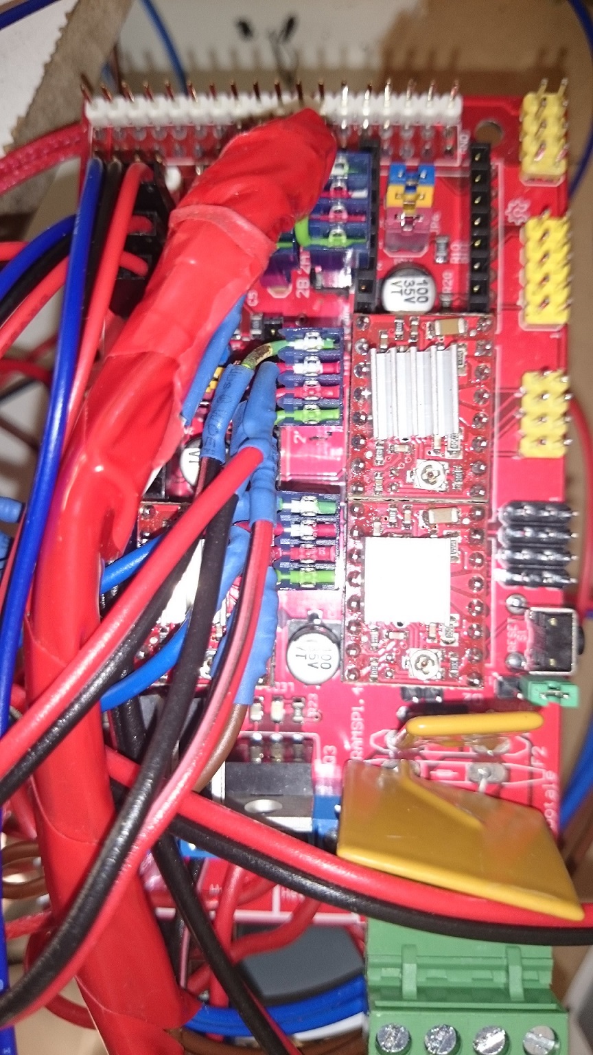
Ya que moi que ca choc ou les pololu sont monté a lenvers ?
A moins que les vrai pololu le potentiometre soit placé differement
Si c est des a4988 alors oui ils sont a l envers
Edited 1 time(s). Last edit at 04/21/2015 02:45AM by One-T.

A moins que les vrai pololu le potentiometre soit placé differement
Si c est des a4988 alors oui ils sont a l envers
Edited 1 time(s). Last edit at 04/21/2015 02:45AM by One-T.
|
Re: Problème de connection moteur April 21, 2015 04:17AM |
Admin Registered: 12 years ago Posts: 2,569 |
Edit pardon mal compris One-T tu parlais de la photo de jeremyfala pas de la tienne ?
C'est vrai que les stepsticks et les pololus n'ont pas le potard du même coté je crois me rappeller, ça peut tromper.
Edited 1 time(s). Last edit at 04/21/2015 04:19AM by DeuxVis.
Most of my technical comments should be correct, but is THIS one ?
Anyway, as a rule of thumb, always double check what people write.

Sorry, only registered users may post in this forum.