Minor Prusa modification
Posted by mikey
|
Minor Prusa modification August 23, 2011 12:18PM |
Registered: 12 years ago Posts: 26 |
During my initail building of the frame I found this to be an issue:
and belt runoff from a slightly canted gear when tightened into place:
Y-axis extended:
Y axis retracted:
The runoff continues until the belt pops off the gearing. If you'll look carefully, you can see the gear tilted slightly differently in the 2 pictures.
To avoid having the belting drag along the all-thread, I added another roller and fender washers on the bottom rod:
By adjusting the roller assembly laterally, any belt runoff from a canted gear on the stepper can also be mitigated.
Edited 1 time(s). Last edit at 08/23/2011 12:19PM by mikey.

and belt runoff from a slightly canted gear when tightened into place:
Y-axis extended:

Y axis retracted:

The runoff continues until the belt pops off the gearing. If you'll look carefully, you can see the gear tilted slightly differently in the 2 pictures.
To avoid having the belting drag along the all-thread, I added another roller and fender washers on the bottom rod:

By adjusting the roller assembly laterally, any belt runoff from a canted gear on the stepper can also be mitigated.
Edited 1 time(s). Last edit at 08/23/2011 12:19PM by mikey.
|
Re: Minor Prusa modification August 23, 2011 01:02PM |
Registered: 12 years ago Posts: 129 |
|
Re: Minor Prusa modification August 23, 2011 01:25PM |
Registered: 12 years ago Posts: 1,611 |
As marnargulus suggests, you can remove the nut between the motor mount and the large washer, bringing the bearing closer to the motor mount.
So long as your Z-axis smooth rod is long enough, you can put the bottom Z-axis support rod UNDER the bottom frame rail, rather than on top, and the belt should run clear of the rod. See Part 5, step 5 of Gary Hodgson's excellent Prusa visual instructions: [garyhodgson.com]
So long as your Z-axis smooth rod is long enough, you can put the bottom Z-axis support rod UNDER the bottom frame rail, rather than on top, and the belt should run clear of the rod. See Part 5, step 5 of Gary Hodgson's excellent Prusa visual instructions: [garyhodgson.com]
|
Re: Minor Prusa modification August 23, 2011 01:48PM |
Registered: 12 years ago Posts: 26 |
Nut removal doesn't solve the belt runoff issue due to a canted gear, as the runoff occurs after several rotational cycles, getting worse every rotation of the gear. The roller also affords me the opportunity to add a small belt tensioner if need be. I followed the assembly instructions to the letter, which was why I had the issue. Reversing the lower rod to under the frame would also require a user to know in advance the vertical rod length needing to be extended unless it was cut to SAE lengths.
|
Re: Minor Prusa modification August 23, 2011 02:14PM |
Registered: 12 years ago Posts: 1,611 |
If you remove the nut between motor mount and bearing, you should be able to reverse the pulley on the motor shaft, so the flange on the end of the pulley holds the belt on, and the belt runs closer to the motor housing rather than on the end of the shaft. Enough, perhaps, to build yourself a new pulley. Or replace it; some people seem to swear by the metal pulleys you can get on ebay. It could be the whole motor that's canted over; the mount may have warped. You can straighten it out by heating it with a hair dryer.
|
Re: Minor Prusa modification August 23, 2011 03:28PM |
Registered: 12 years ago Posts: 6 |
I've also seen people use cable ties to hold the motor body parallel to the threaded rod. If there's too much flex in your motor mount, that's a quick and easy solution. I left out that nut as well as it didn't seem to make sense to have the belt that far out from the motor body.
I got stuck with the smooth rods being too short to mount the cross piece underneath just like you. But I have the belt running over top of the threaded rod, and just stuck a nylon standoff over the rod to prevent wear. I like your solution too, but I didn't have a spare bearing.
.: repraponaut.blogspot.com :.
|
Re: Minor Prusa modification August 23, 2011 04:06PM |
Registered: 12 years ago Posts: 26 |
droftarts Wrote:
-------------------------------------------------------
> If you remove the nut between motor mount and
> bearing, you should be able to reverse the pulley
> on the motor shaft, so the flange on the end of
> the pulley holds the belt on, and the belt runs
> closer to the motor housing rather than on the end
> of the shaft. Enough, perhaps, to build yourself a
> new pulley. Or replace it; some people seem to
> swear by the metal pulleys you can get on ebay. It
> could be the whole motor that's canted over; the
> mount may have warped. You can straighten it out
> by heating it with a hair dryer.
The mount was pretty square when I checked it and decided the gear was the issue. I also like the idea of metal gears, and did some searching for the pitch/diameter of the gears. As for removing the nut, I do not relish re-trueing that thing again, so I'll pass. Might be something to update the assembly instructions with for future builders.
argocapn Wrote:
-------------------------------------------------------
> I've also seen people use cable ties to hold the
> motor body parallel to the threaded rod. If
> there's too much flex in your motor mount, that's
> a quick and easy solution. I left out that nut as
> well as it didn't seem to make sense to have the
> belt that far out from the motor body.
>
> I got stuck with the smooth rods being too short
> to mount the cross piece underneath just like you.
> But I have the belt running over top of the
> threaded rod, and just stuck a nylon standoff over
> the rod to prevent wear. I like your solution too,
> but I didn't have a spare bearing.
When I get back to it, I'll look into stiffening the mount to see if it requires it. I got the bearing at the local Ace hardware, but not everybody has a hardware store a few blocks away. I initially thought about a nylon bushing too, but I also needed the fender washers for the lateral adjustment, so I went with the roller. The extra $6 seemed worth it considering the expense and time I already have in it.
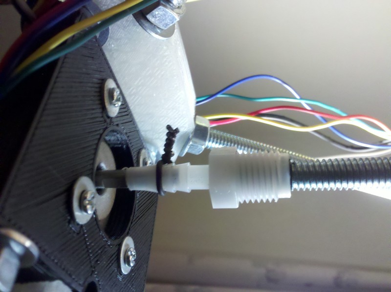
This isn't the only modification I have done. I also added a 3/32" roll pin through the all-hread and the Z-axis connector to stop the all-thread from slipping in the connector body:
I could get a great bite on the stepper motor stem, but no matter how tight I got the all-thread joint, it sliiped, and it felt as though I was starting to reach the limit of tolerance on tightening and not having some failure of the connector due to over-torquing the allen bolts that hold it closed.
I may use some cheapy McMaster-Carr Acme threaded rod and ball screws to see if I can have the axes run on that as opposed to the drill rod, belting and all-thread. It's more expensive, but isn't this entire exercise all about taking something and making it better?
Last thing I'm doing (mechanically anyway) is cleaning up the wiring. I had issues finding the 2.54mm plug bodies in stock, so I ordered 100 3's and 100 4's along with a bazzillion pin inserts from Mouser so I can do a clean wire job, and I'm making an adapter board for the Z-axis parallel wiring so I can connect everything right to the main board and be done with it.
Once all that is done, I get to decipher the jigsaw puzzle that the firmware/software seems to be.
Edited 1 time(s). Last edit at 08/23/2011 04:08PM by mikey.
-------------------------------------------------------
> If you remove the nut between motor mount and
> bearing, you should be able to reverse the pulley
> on the motor shaft, so the flange on the end of
> the pulley holds the belt on, and the belt runs
> closer to the motor housing rather than on the end
> of the shaft. Enough, perhaps, to build yourself a
> new pulley. Or replace it; some people seem to
> swear by the metal pulleys you can get on ebay. It
> could be the whole motor that's canted over; the
> mount may have warped. You can straighten it out
> by heating it with a hair dryer.
The mount was pretty square when I checked it and decided the gear was the issue. I also like the idea of metal gears, and did some searching for the pitch/diameter of the gears. As for removing the nut, I do not relish re-trueing that thing again, so I'll pass.
Might be something to update the assembly instructions with for future builders. argocapn Wrote:
-------------------------------------------------------
> I've also seen people use cable ties to hold the
> motor body parallel to the threaded rod. If
> there's too much flex in your motor mount, that's
> a quick and easy solution. I left out that nut as
> well as it didn't seem to make sense to have the
> belt that far out from the motor body.
>
> I got stuck with the smooth rods being too short
> to mount the cross piece underneath just like you.
> But I have the belt running over top of the
> threaded rod, and just stuck a nylon standoff over
> the rod to prevent wear. I like your solution too,
> but I didn't have a spare bearing.
When I get back to it, I'll look into stiffening the mount to see if it requires it. I got the bearing at the local Ace hardware, but not everybody has a hardware store a few blocks away. I initially thought about a nylon bushing too, but I also needed the fender washers for the lateral adjustment, so I went with the roller. The extra $6 seemed worth it considering the expense and time I already have in it.
This isn't the only modification I have done. I also added a 3/32" roll pin through the all-hread and the Z-axis connector to stop the all-thread from slipping in the connector body:

I could get a great bite on the stepper motor stem, but no matter how tight I got the all-thread joint, it sliiped, and it felt as though I was starting to reach the limit of tolerance on tightening and not having some failure of the connector due to over-torquing the allen bolts that hold it closed.
I may use some cheapy McMaster-Carr Acme threaded rod and ball screws to see if I can have the axes run on that as opposed to the drill rod, belting and all-thread. It's more expensive, but isn't this entire exercise all about taking something and making it better?
Last thing I'm doing (mechanically anyway) is cleaning up the wiring. I had issues finding the 2.54mm plug bodies in stock, so I ordered 100 3's and 100 4's along with a bazzillion pin inserts from Mouser so I can do a clean wire job, and I'm making an adapter board for the Z-axis parallel wiring so I can connect everything right to the main board and be done with it.
Once all that is done, I get to decipher the jigsaw puzzle that the firmware/software seems to be.
Edited 1 time(s). Last edit at 08/23/2011 04:08PM by mikey.
|
Re: Minor Prusa modification August 23, 2011 06:38PM |
Registered: 16 years ago Posts: 824 |
|
Re: Minor Prusa modification August 24, 2011 02:25AM |
Registered: 13 years ago Posts: 228 |
Running out of the stock of zip ties (and sometimes of patience) here.
I have found the belt slipping along the pulley problem to be actually related to the flexion of the motor mount (happens with the y motor mount, but also with the X motor mount) under the (still moderate) tension of the belt. Disclaimer: I am _not_ overtensioning those belts, they are optimized to be used with some tension!
I have aluminium machined pulleys and the slipping is still observable, although the pulleys increased length does not allow for the belt to totally slip out. Anyway, slipping is bothersome enough, belts, especially the X one, get well out of their intended axis. All of this could be easily solved by putting back plastic where it is structurally needed! (and we'll save quite some time and zip ties). I'll try to help with redesigning some parts. Designers, wake up! You have gone too far with some reductions in plastic!
Interim solutons:
- a stiffer mount for the Y axis motor. For starters, I did not even bother to slip in the wimpy plastic part, went for a 6.7 mm routed plywood piece instead. based on Adrian's mod. Still not stiff enough (hence the zip ties), you should go go for at least 8 mm, be it plywood, MDF or printed.
Checking old files: Mendel's massive Y bracket was 17.5 mm thick!
- a stiffer mount for the X axis motor. Redesign is non-trivial, need some more time. I had to resort to the pictured crummy solution for now.
- And yesterday night I added an X pulley cap, design is enclosed. (sorry, print quality of the latter is dismal, got a significant quality reversal dialing in different values for E reversal to deal with residual blobbing & strings)
I also had to resort to fixing the transversal bar on top of the longitudinal ones, just like you, because of Z rod length issues. 330mm rods are much easier to get that other dimensions, the recommended build probably should be stabilized around those lengths.
solutions:
Installing printed idlers over the bearings (they are needed anyway since the bearing-plus-big-washer solution is quite inappropriate and the belts get frequently caught inside the ridges between the bearing and the washers causing increased friction) helps to get the belt out of the way. Initially, I also had added an idler on the transversal bar, but got rid of it after installing the printed idlers at both ends. I wrapped the middle of the transversal bar in some turns of kapton tape to deal with any occasional contact.
Conclusions? I have still not commissioned my Mendel Prusa to print, since I want to solve the obvious design shortcomings first, and I feel it has the potential to be a superior machine. Using the pirated cupcake for printing, for all means it has become by now a stable workhorse. Cheers!
x_pulley_cap.scad
x_pulley_cap.stl
Edited 4 time(s). Last edit at 08/24/2011 04:49AM by Lanthan.
I have found the belt slipping along the pulley problem to be actually related to the flexion of the motor mount (happens with the y motor mount, but also with the X motor mount) under the (still moderate) tension of the belt. Disclaimer: I am _not_ overtensioning those belts, they are optimized to be used with some tension!
I have aluminium machined pulleys and the slipping is still observable, although the pulleys increased length does not allow for the belt to totally slip out. Anyway, slipping is bothersome enough, belts, especially the X one, get well out of their intended axis. All of this could be easily solved by putting back plastic where it is structurally needed! (and we'll save quite some time and zip ties). I'll try to help with redesigning some parts. Designers, wake up! You have gone too far with some reductions in plastic!
Interim solutons:
- a stiffer mount for the Y axis motor. For starters, I did not even bother to slip in the wimpy plastic part, went for a 6.7 mm routed plywood piece instead. based on Adrian's mod. Still not stiff enough (hence the zip ties), you should go go for at least 8 mm, be it plywood, MDF or printed.
Checking old files: Mendel's massive Y bracket was 17.5 mm thick!
- a stiffer mount for the X axis motor. Redesign is non-trivial, need some more time. I had to resort to the pictured crummy solution for now.
- And yesterday night I added an X pulley cap, design is enclosed. (sorry, print quality of the latter is dismal, got a significant quality reversal dialing in different values for E reversal to deal with residual blobbing & strings)
I also had to resort to fixing the transversal bar on top of the longitudinal ones, just like you, because of Z rod length issues. 330mm rods are much easier to get that other dimensions, the recommended build probably should be stabilized around those lengths.
solutions:
Installing printed idlers over the bearings (they are needed anyway since the bearing-plus-big-washer solution is quite inappropriate and the belts get frequently caught inside the ridges between the bearing and the washers causing increased friction) helps to get the belt out of the way. Initially, I also had added an idler on the transversal bar, but got rid of it after installing the printed idlers at both ends. I wrapped the middle of the transversal bar in some turns of kapton tape to deal with any occasional contact.
Conclusions? I have still not commissioned my Mendel Prusa to print, since I want to solve the obvious design shortcomings first, and I feel it has the potential to be a superior machine. Using the pirated cupcake for printing, for all means it has become by now a stable workhorse. Cheers!
x_pulley_cap.scad
x_pulley_cap.stl


Edited 4 time(s). Last edit at 08/24/2011 04:49AM by Lanthan.
|
Re: Minor Prusa modification August 24, 2011 12:38PM |
Registered: 12 years ago Posts: 26 |
Why not just have a printed piece at the rear of the motor that would screw into 2 of the holes in the back of the stepper? It wouldn't have to be very structurally large, it would simply be a piece tying the rear to the cross member for stability.
BTW, love the printed spool concept.
Edited 2 time(s). Last edit at 08/24/2011 12:41PM by mikey.
BTW, love the printed spool concept.
Edited 2 time(s). Last edit at 08/24/2011 12:41PM by mikey.
|
Re: Minor Prusa modification August 24, 2011 12:47PM |
Registered: 13 years ago Posts: 632 |
|
Re: Minor Prusa modification August 24, 2011 01:35PM |
Registered: 13 years ago Posts: 228 |
@mikey: was mulling something around that at the beginning, but now I think there's a much better solution.
I am working on a torsion box mount for the y axis that would only require one 12x28x8 bearing and three m3x40 bolts , secure the pulley on both sides, seriously reduce forces exerted on the motor bearing, and would not require whole truckloads of plastic. I think the concept could easily be extended to the X axis too.
More on this (and hopefully stls, will release "unproven", mail-ordered the bearings only today) later.
|
Re: Minor Prusa modification August 24, 2011 02:03PM |
Registered: 12 years ago Posts: 1,611 |
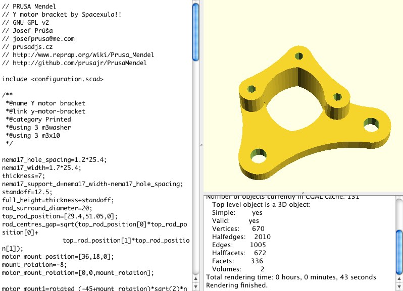
As an alternative bracket, there's Spacexula's version which has a stand-off for the motor, so the belt can go right next to the motor, which might work better for you. See attached image. I found it in Greg Frost's github archive here: [github.com]
Of course, you'll need to get your printer working to print it...
Of course, you'll need to get your printer working to print it...
|
Re: Minor Prusa modification August 24, 2011 04:27PM |
Registered: 13 years ago Posts: 228 |
OK, here it is.
Starting point was the dxf of Adrian's modified Y mount.
Easy to print, should provide a more stable Y mount, since the pulley will be supported from both ends.
you'll need 3 m3x40 bolts and two m3x8, and one 12x28x8 bearing, 6001RS or similar.
There's a gazillion ways of improving it.
Shoudn't be too hard to modify an printable pulley to fit in the bearing hole, or to adopt a different bearing.
The printer's heating.
ybracmod_mount.stl
ybracmod_cover.stl
ybracproj_extr.dxf
ybracproject.dxf
configuration.scad
ybracproj1.scad


Starting point was the dxf of Adrian's modified Y mount.
Easy to print, should provide a more stable Y mount, since the pulley will be supported from both ends.
you'll need 3 m3x40 bolts and two m3x8, and one 12x28x8 bearing, 6001RS or similar.
There's a gazillion ways of improving it.
Shoudn't be too hard to modify an printable pulley to fit in the bearing hole, or to adopt a different bearing.
The printer's heating.
ybracmod_mount.stl
ybracmod_cover.stl


ybracproj_extr.dxf
ybracproject.dxf
configuration.scad
ybracproj1.scad
|
Re: Minor Prusa modification August 24, 2011 05:05PM |
Registered: 12 years ago Posts: 26 |
|
Re: Minor Prusa modification August 24, 2011 05:16PM |
Registered: 13 years ago Posts: 228 |
as per the pictures: motor gets bolted "behind" ybracmod_mount, then comes the pulley and the idler with some number of washers, then ybrac_cover with the bearing inserted on ybrac_cover, and the end of the pulley inserted in the bearing.
You secure it al with bolts that go either to the stepper or all the way through. Belt has enough clearance to pass between the "pillars". I'll print and post pictures. Cheers.
You secure it al with bolts that go either to the stepper or all the way through. Belt has enough clearance to pass between the "pillars". I'll print and post pictures. Cheers.
|
Re: Minor Prusa modification August 24, 2011 05:32PM |
Registered: 12 years ago Posts: 26 |
|
Re: Minor Prusa modification August 25, 2011 06:03AM |
Registered: 13 years ago Posts: 228 |
Printed. Now waiting for the bearing.
Released on Thingiverse: [www.thingiverse.com]
Any help with the audit/redesign effort most welcome.
Released on Thingiverse: [www.thingiverse.com]
Any help with the audit/redesign effort most welcome.
|
Re: Minor Prusa modification August 26, 2011 12:40AM |
Registered: 12 years ago Posts: 50 |
Hey man.
Good work on the mods.
Check these pics out.
I didnt like the single smooth rod on the Z axis, so i got some more smooth rod and made it into 2.
Im going to right it all up later.
I just started printing.
Like litterally im on cube 5 right now.
Also instead of PLA bushings, I found some perfect fitting nylon spacers that just allow smoothest motion and very little lash.
And in the second pic is of the Z axis threaded rods attached the motors.
Its a threaded nipple for a pipe to tubing conversion.
1/4" male iron pipe to 1/4" Barb.
5mm drill bit to ream out the barb end and a little electrical tape on the all thread and its working great.
At first it was slipping so i added some bailing wire.
Works well,
Oakie rigged but it will do for now.
|
Re: Minor Prusa modification August 26, 2011 06:39AM |
Registered: 13 years ago Posts: 228 |
@420e: Hacks on the grand tradition!
Funny, yesterday I was also mulling around the idea of two z rods per side instead of one.
...also doubling the X rods with 2 threaded M8 or M10 1.5cm in the same plane, a bit outside the smooth rods..
Will need to mature that, and balance it with the dietary requirements...
And yeah, printed pieces should all fit in a 100x95 bed, helps stay (more or less) sane.
This stuff is highly addictive.
|
Re: Minor Prusa modification August 26, 2011 07:36AM |
Admin Registered: 17 years ago Posts: 7,879 |
What keeps the X axis level front to back? With the original single rod design there are bushings top and bottom to stop it twisting. All I can see two z-rods doing is cause binding if they are not precisely parallel.
On my redesign I have dropped the motor and the idler so their axis is in line with the bars. That way there is no bending force from the belt tension.
[www.hydraraptor.blogspot.com]
On my redesign I have dropped the motor and the idler so their axis is in line with the bars. That way there is no bending force from the belt tension.
[www.hydraraptor.blogspot.com]
|
Re: Minor Prusa modification August 26, 2011 08:29AM |
Registered: 13 years ago Posts: 228 |
|
Re: Minor Prusa modification August 26, 2011 08:36AM |
Registered: 12 years ago Posts: 1,611 |
If the X-axis rods were clamped solidly in the X-end holder, tensioning the X-axis belt would not pull the Z-axis rod in, and an additional Z rod would not be needed. That's why I'm not a fan of the current push-together X axis holders - they need a clamp. Tightening the Y axis can pull the threaded rod in as well; it might be worth fitting a strengthening rod across, like the lower Z rod support, if there is space under your Y axis.
Also, if your motor mount is twisting, you can straighten up your motors and fix the pulley run out with a couple of washers between the motor and the mount, on the 3mm motor mounting bolts, but just on one side (whichever way it needs adjusting).
Also, if your motor mount is twisting, you can straighten up your motors and fix the pulley run out with a couple of washers between the motor and the mount, on the 3mm motor mounting bolts, but just on one side (whichever way it needs adjusting).
|
Re: Minor Prusa modification August 26, 2011 11:07AM |
Registered: 13 years ago Posts: 228 |
droftarts Wrote:
-------------------------------------------------------
> If the X-axis rods were clamped solidly in the
> X-end holder,
Got that solved. This provides a decent grip on the smooth rods, if installed on both ends,
[www.reprap.org]
at low cost. Just make sure to drill (2.5 mm) and tap (M3) a couple of faces 120 degrees apart, and not 180 as I did.
> tensioning the X-axis belt would not
> pull the Z-axis rod in, and an additional Z rod
> would not be needed. That's why I'm not a fan of
> the current push-together X axis holders - they
> need a clamp.
Clamping force must be higher than what is provided by the plastic tabs.
GregFrost further refined that plastic tab concept by providing optional closed ends "adjustable" with axial nut traps. Still I am not sure it is the way to go.
As for me, I'd prefer to go back to bolted-in clamping pieces for the rods. But there is little clearance to do it right, and monolithic design provides (maybe) some structural advantages..
>Tightening the Y axis can pull the
> threaded rod in as well; it might be worth fitting
> a strengthening rod across, like the lower Z rod
> support, if there is space under your Y axis.
There is space indeed (I have installed the middle transversal over the rods because of Z rod lengths issues).
Also: Looking at the Selis Mendel designs, there are pieces on both Y ends connecting both threaded rods in the middle. The Y motor mount is providing this on one side. For the other end, one might design something to be slipped and tightened on both sides of the idler.
Using the old but proven double nut system has an additional benefit: increases rigidity (as compared with self-blocking nut)
>
> Also, if your motor mount is twisting, you can
> straighten up your motors and fix the pulley run
> out with a couple of washers between the motor and
> the mount, on the 3mm motor mounting bolts, but
> just on one side (whichever way it needs
> adjusting).
Will work, but not entirely satisfying, because the lack of rigidity will still promote vibrations. I'm completing a redesign of the X motor mount with the pulley encased in a torsion box, plus an 8 mm thick motor wall - and I am quite tempted to add also one single threaded bar connecting the torsion boxes on both ends. Unobstrusive and just over the belt. At least I'll leave this possibility in the design, like the rest, that would provide an optional upgrade path...
|
Re: Minor Prusa modification August 26, 2011 02:29PM |
Registered: 12 years ago Posts: 1,611 |
Thanks Lanthan, your mods are sensible! I'm keen to move to a vertically stacked X-axis rods layout, like the Russian one here [translate.google.co.uk] and the one Emmanuel is working on [reprap.org]. I think these solve the X motor rigidity problem, and more tightly constrain the X-axis bars to the Z-axis rod.
|
Re: Minor Prusa modification August 26, 2011 05:33PM |
Registered: 12 years ago Posts: 26 |
|
Re: Minor Prusa modification August 27, 2011 03:22AM |
Registered: 13 years ago Posts: 1,352 |
Honestly, if any1 wants to make the Zbars vertical, can i have a suggestion? Simply making a double X axis seems better in terms of equilibrium on each side of Z rods, and pretty cheap. Basically it would look like 4 smooth rods in a square / rectangle placement, and then both X terminations can be exactly the same piece, each with a motor and an idler facing the other end.
So dual carriages and dual extruders, independent on each other except they would be on same Z. Having issues with an extruder -print with the other one. Or have different filaments or nozzles.
On carriage can be parked when the other is used, but also a further interesting thought is, why would i bother finding extra pins for second Y motor, just hook it up along with initial Z, just will move in reverse each time, so when one will make a directional move and stop, the other will make the same in the opposite direction at exact same time and probably would help with some inertial dampening or something like that, keeping X steadier overall. Haha, dunno if it would actually work like that but it just might - if the end pieces are strong and rigid enough.
Edit:
Also another point, in original prusa files for those parts, the Z nut that is engaging the movements for Z axis is on the lower part and by default one can only use a very small nut. There are "coupling" nuts (i think thats the name, not sure), that are much taller, like 4-5 normal nuts placed each on top of each other. That should be better to use, so the point where the nut is trapped inside the hexagonal ring should be moved upwards a few cm.
Edit2:
I would also incorporate the doubler mod [www.thingiverse.com] in both axis X and Y to be used by default. I think its worthy and all machines should have it. Y mount can be also made wider like 2 cm, only in the area where its clamped to structural bars, in rest can be like 7-8mm or so (motor area), and i believe that would make it stiff enough.
Edited 4 time(s). Last edit at 08/27/2011 03:43AM by NoobMan.
|
Re: Minor Prusa modification August 27, 2011 06:46AM |
Registered: 13 years ago Posts: 228 |
@mikey & droftarts: thank you guys for the kind words! Just having a lot of fun re-learning some modelling after a very, very long pause. The printer adds some magick to it.
@NoobMan: Yes, the long Z nuts, tried 'em at the very start, you can see 'em in "old" pictures like her: [www.thingiverse.com] , but the testing got totally obscured by Z motor power distribution problems until I wired 'em serial. In the mean time I had replaced the coupling nuts by normal nuts to reduce friction.
From that experience: the longitudinal play of the nut on the rod feels very similar as that of "standard" nuts. But backlash shouldn't be much of a problem since the Z axis is constantly preloaded by the weight of all the stuff residing on it, and travel along Z is (usually) one-way. My provisory conclusion is that the benefit provided by long nuts would be quite marginal. And we don't want to transfer lateral forces to that woobly axis.
2 Z rods: would provide us with a centered path for the belt in the middle.
At the cost of added viamins.
Yes I am also following closely the nice work of Emmanuel and the Cypress guys.
About my mods: I have found myself trying to keep 'em as much as possible compatible with the existing setup and clearances, so as to provide a path for upgrade from a "standard" configuration without the need of re-touching the parts that (apparently) work well. I am not yet desperate enough to want to re-cut or re-print my X carriage.
This option of course poses limits on design freedom, just like reuse of other people's code. Sometimes it is more satisfying and straightforward to start with a clean, fresh slate.
I am not happy with the current state of this mod: much time spent trying to keep some existing features and code. Some might need to be dropped in the end. No rounded corners, and the code is still a disgusting mess. Will clean up a bit before posting.
the x-end-motor-mod basically provides a stronger (8mm) wall for the motor, and an H structure should provided increased rigidity. Somehow addresses concerns about play between the different planes.
Stuff I am not yet sure about:
- the LM8UU clip mount
- and above all the cuts along the lower surface (GregFrost's), I'm concerned about their impact on stiffness.
What would you do?
the x-motor-cover is based on a torsion box idea (like the Y), and optionally can be fitted with one or two threaded rods (or maybe also smooth?) that run along the belt and join both x-ends. (still missing: the idler end & cover designs, shouldn't be hard). The x motor's pulley is supported in both side, and there is a 10 mm clearance for the belt.
When carefully adjusted, fitted with the 2 additional rods and bolted together, both parts should provide a rigid L (as in "Lanthan" ) structure
Must check clearances with the carriage and limits to Z travel height.
Please analyze and comment.
Cheers,
x_motor_cover.stl
x-end-motor-mod.stl
Edited 2 time(s). Last edit at 08/27/2011 08:05AM by Lanthan.
@NoobMan: Yes, the long Z nuts, tried 'em at the very start, you can see 'em in "old" pictures like her: [www.thingiverse.com] , but the testing got totally obscured by Z motor power distribution problems until I wired 'em serial. In the mean time I had replaced the coupling nuts by normal nuts to reduce friction.
From that experience: the longitudinal play of the nut on the rod feels very similar as that of "standard" nuts. But backlash shouldn't be much of a problem since the Z axis is constantly preloaded by the weight of all the stuff residing on it, and travel along Z is (usually) one-way. My provisory conclusion is that the benefit provided by long nuts would be quite marginal. And we don't want to transfer lateral forces to that woobly axis.
2 Z rods: would provide us with a centered path for the belt in the middle.
At the cost of added viamins.
Yes I am also following closely the nice work of Emmanuel and the Cypress guys.
About my mods: I have found myself trying to keep 'em as much as possible compatible with the existing setup and clearances, so as to provide a path for upgrade from a "standard" configuration without the need of re-touching the parts that (apparently) work well. I am not yet desperate enough to want to re-cut or re-print my X carriage.
This option of course poses limits on design freedom, just like reuse of other people's code. Sometimes it is more satisfying and straightforward to start with a clean, fresh slate.


I am not happy with the current state of this mod: much time spent trying to keep some existing features and code. Some might need to be dropped in the end. No rounded corners, and the code is still a disgusting mess. Will clean up a bit before posting.
the x-end-motor-mod basically provides a stronger (8mm) wall for the motor, and an H structure should provided increased rigidity. Somehow addresses concerns about play between the different planes.
Stuff I am not yet sure about:
- the LM8UU clip mount
- and above all the cuts along the lower surface (GregFrost's), I'm concerned about their impact on stiffness.
What would you do?
the x-motor-cover is based on a torsion box idea (like the Y), and optionally can be fitted with one or two threaded rods (or maybe also smooth?) that run along the belt and join both x-ends. (still missing: the idler end & cover designs, shouldn't be hard). The x motor's pulley is supported in both side, and there is a 10 mm clearance for the belt.
When carefully adjusted, fitted with the 2 additional rods and bolted together, both parts should provide a rigid L (as in "Lanthan"
) structure Must check clearances with the carriage and limits to Z travel height.
Please analyze and comment.
Cheers,


x_motor_cover.stl
x-end-motor-mod.stl
Edited 2 time(s). Last edit at 08/27/2011 08:05AM by Lanthan.
|
Re: Minor Prusa modification August 27, 2011 08:12AM |
Admin Registered: 17 years ago Posts: 7,879 |
Lanthan Wrote:
-------------------------------------------------------
> Nophead,
>
> Suspense is building up.
> Could we have a peek look at your redesign?
> (when?)
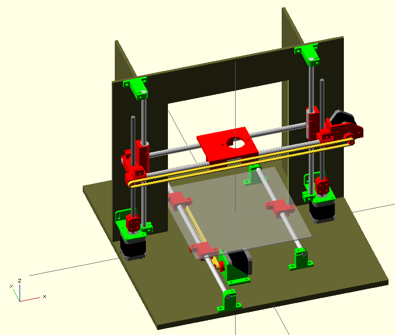
This is what it looks like at the moment.
It still have to add belt anchors / endstops, etc. The design is fully parametric and is shown with 10MM rods and an overall volume the same as Mendel. That gives a 200x 200 build area but a very tall Z axis so I will probably make it a lot lower. An advantage of not using the triangular frame means all the axis sizes are independent of each other and are just a matter of changing the sheets and rod lengths.
The Y axis belt is half the length by putting the motor and idler under the bed. Since they are screwed to 12mm MDF sheet (instead of hung from springy bars) they can take any amount of belt tension without moving.
The Z bars are also attached to rigid sheet so should be able to the X axis impulses without moving. I might make the top bar clamps triangular if they prove not stiff enough.
The X motor and idler at the same level as the bar, so the tension will not bend the bars.
Edited 1 time(s). Last edit at 08/27/2011 08:14AM by nophead.
[www.hydraraptor.blogspot.com]
-------------------------------------------------------
> Nophead,
>
> Suspense is building up.
> Could we have a peek look at your redesign?
> (when?)
This is what it looks like at the moment.

It still have to add belt anchors / endstops, etc. The design is fully parametric and is shown with 10MM rods and an overall volume the same as Mendel. That gives a 200x 200 build area but a very tall Z axis so I will probably make it a lot lower. An advantage of not using the triangular frame means all the axis sizes are independent of each other and are just a matter of changing the sheets and rod lengths.
The Y axis belt is half the length by putting the motor and idler under the bed. Since they are screwed to 12mm MDF sheet (instead of hung from springy bars) they can take any amount of belt tension without moving.
The Z bars are also attached to rigid sheet so should be able to the X axis impulses without moving. I might make the top bar clamps triangular if they prove not stiff enough.
The X motor and idler at the same level as the bar, so the tension will not bend the bars.
Edited 1 time(s). Last edit at 08/27/2011 08:14AM by nophead.
[www.hydraraptor.blogspot.com]
|
Re: Minor Prusa modification August 27, 2011 11:27AM |
Registered: 13 years ago Posts: 228 |
I like it:
Reduced parts count,
Increased freedom,
Simplification is good!
MDF, optionally stabilized by epoxy, is a winner.
For increased rigidity: At some point you might feel the need to box those two vertical pieces in the YZ plane with an horizontal piece over the top.
...
Side thoughts:
Am I glad I purchased as large a CNC router as I could afford instead of that BFB thingie

Sorry, only registered users may post in this forum.