Motion system evaluation process for new printers
Posted by Bill Clark
|
Motion system evaluation process for new printers April 01, 2018 05:34PM |
Registered: 10 years ago Posts: 239 |
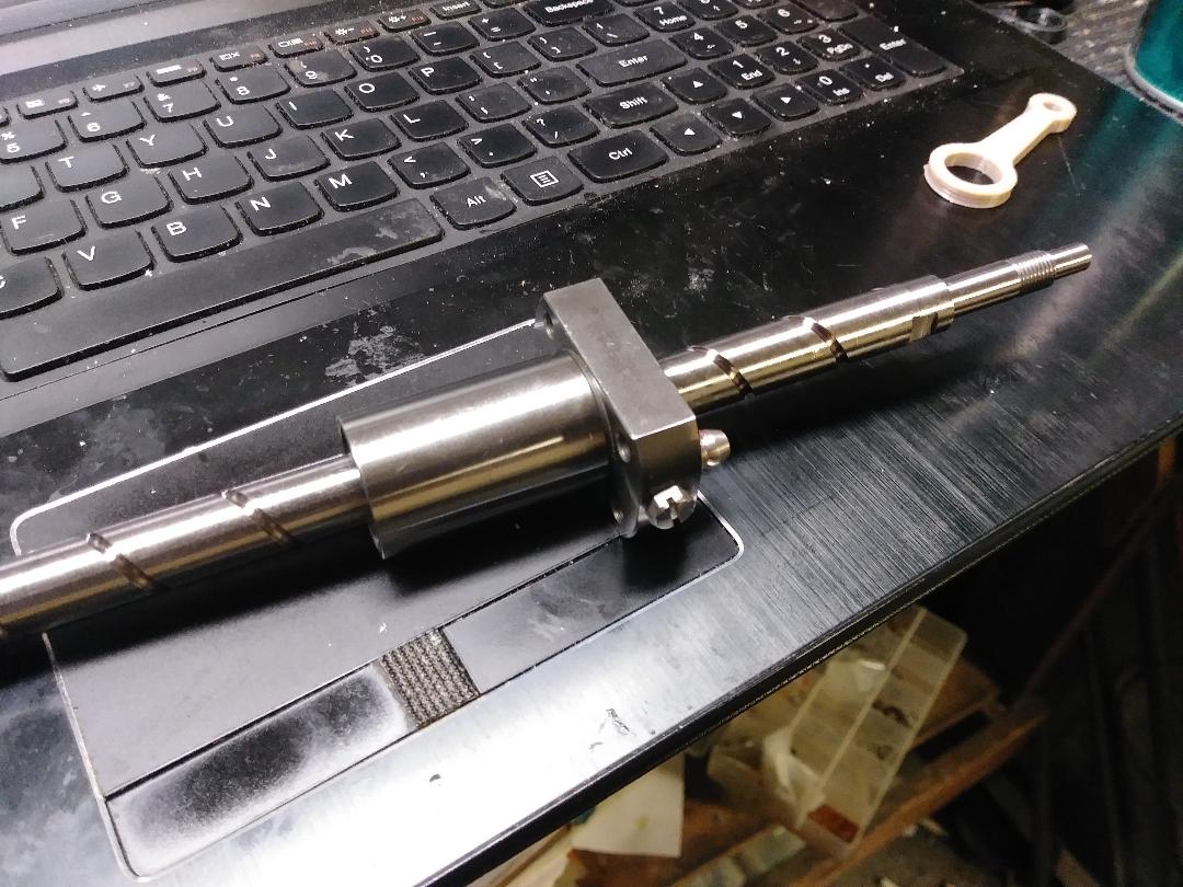
I have spent the last several weeks setting up a test fixture to evaluate different ball screw lead/motor combinations, define maximum performance for said combination and to gain a better understanding of this type of motion system in general. Thankfully the Duet Ethernet affords the ability to run high step rates allowing a broader range of combinations. In the interest of efficiency i.e. wasting as little time as possible, I am looking for some input on a process to evaluate and determine:
- maximum accel and ISC (instant speed change aka Jerk) for different speeds and distances
-Factoring accel/ISC, will programmed speed actually be achieved?
-What will be the average speed
-Better understand ISC. I thought I would see a jump at the beginning of the motion profile to the point where acceleration began but thats not the case
-where to go from where I am at i.e. different motor, different screw lead
I have been working so hard to get all of this together that my brain is not coming up with a clear path as to exactly what I am trying to achieve and how to go about it.
Realizing that the printing speed will be more of a function of how fast plastic can be pumped out of the nozzle, I think non printing moves over short and long distances is where a large benefit will be seen. That and making certain I have the best combination possible for the task at hand.
To accumulate data I have the fixture itself, a high speed video camera capable of 1000 fps but so far setting it to 480 fps seems to offer adequate sampling rate to view the dial caliper I have mounted to the fixture and also a data logger that can provide volts, amps, motor rpm temperature and an accelerometer. The data recorder can only sample at 80hz so its going to miss some stuff. I tried a digital readout for the positioning but the calipers showed the best results with accuracy and repeatability of .04mm or better as you can see in this video [youtu.be] . If you slow down the portion of the video with the dial to quarter speed you can clearly see the accel/deccel. In my original video I can go frame by frame an measure the time for different segments.(.00208 seconds per frame at @ 480fps and .001 @ 1000fps) I have validated the accuracy of this method.
The combination in the video is 24v, a Motech MT-1704HSM168RE with 4.4kg-cm,1.65 ohms, 2.9 mH inductance, set to 85% of the 1.68 rated current carrying 3kg of ballast (est weight of the heaviest axis). Looking at Motechs website this appears to be a midrange speed motor. The screw has a 10mm lead.This combination is quit (no rattling on direction change) and reliable up to 12000mm/m (1200rpm) with 3kg ballast and Accel/jerk set to 2000/600 and 6000mm/m (600rpm) with accel/jerk set to 5000/1500. Reduce the ballast to 1.5kg and over 18000mm/m (1800rpm) is no problem.
I was thinking of trying a sub 3 amp nema 23 low inductance motor next. The Duet can handle it and they appear to have a much higher RPM range than the 17's not that I probably need much more than 18000mm/m but the torque will be higher up high. But how will a 23 cope with low speeds?. Also thinking of trying a 15 or 20mm lead to get the nema 17 closer to its sweet spot but I will loose torque multiplication by going to a higher lead. A lower inductance nema 17 would be another option but I cant seem to find one except for a Motech .1704HDM250AW and they dont respond to emails for availability. I know thats a lot to digest, but, thoughts?
|
Re: Motion system evaluation process for new printers April 02, 2018 02:26AM |
Registered: 9 years ago Posts: 5,232 |

|
Re: Motion system evaluation process for new printers April 02, 2018 12:25PM |
Registered: 10 years ago Posts: 239 |
|
Re: Motion system evaluation process for new printers April 02, 2018 12:46PM |
Registered: 11 years ago Posts: 5,780 |
I have a 10 mm pitch ball screw driving the Y axis in SoM. It uses a 425 oz-in NEMA-23 motor, DSP driver, and 32V power supply. It can run pretty fast- 80-100 mm/sec, however, at about 50 mm/sec it has a mechanical resonance that causes the motor to skip steps (and make a LOT of noise). In a 3D printer, the mechanism has to run over a wide range of speeds. If SoM is printing a cylinder, even with print speed set to 100 mm/sec, the speed has to drop to under 50 mm/sec at the front and back sides of the cylinder. When the speed passes through the resonance, it skips and the print fails. The only way to keep it working is to operate below that resonance, so we keep the speed- all speeds- down to 40 mm/sec or less (and prints come out great!). I have tried all sorts of things (inertial dampers, super high microstepping, rubber motor mount, etc.) to suppress the resonance and never found anything that would do the job.
Ultra MegaMax Dominator 3D printer: [drmrehorst.blogspot.com]
Ultra MegaMax Dominator 3D printer: [drmrehorst.blogspot.com]
|
Re: Motion system evaluation process for new printers April 02, 2018 04:38PM |
Registered: 10 years ago Posts: 239 |
I remember you mentioning the resonance issue and was anticipating it but not seen or heard even a trace. I have tried both 1.8 and .9 motors at the 16x ms (interpolated) which is preferred setting for the Duets drivers. It is super quit with the .9 motors. I think the lack of resonance is either the drivers or the fact that its bolted to a huge chunk of solid aluminum. This is with a solid aluminium motor coupler.also been from 0 to over 300 mm/s and everywhere in between and run a few old g code programs from previously printed parts.my printer design for this motion system will use 1 1/2 welded steel barstock for the frame for rigidity and in the hope avoiding resonance
|
Re: Motion system evaluation process for new printers April 02, 2018 04:48PM |
Registered: 10 years ago Posts: 14,672 |
@digital_dentist, did you find out what is resonating? Could it be transverse vibrations of the leadscrew itself, when the distance between the motor and the leadscrew nut is large? Such vibrations would be readily excited if the leadscrew is very slightly out of alignment with the motor shaft, due to a poorly made coupling.
Edited 1 time(s). Last edit at 04/02/2018 04:49PM by dc42.
Large delta printer [miscsolutions.wordpress.com], E3D tool changer, Robotdigg SCARA printer, Crane Quad and Ormerod
Disclosure: I design Duet electronics and work on RepRapFirmware, [duet3d.com].
Edited 1 time(s). Last edit at 04/02/2018 04:49PM by dc42.
Large delta printer [miscsolutions.wordpress.com], E3D tool changer, Robotdigg SCARA printer, Crane Quad and Ormerod
Disclosure: I design Duet electronics and work on RepRapFirmware, [duet3d.com].
|
Re: Motion system evaluation process for new printers April 02, 2018 07:09PM |
Registered: 10 years ago Posts: 239 |
|
Re: Motion system evaluation process for new printers April 02, 2018 07:31PM |
Registered: 10 years ago Posts: 14,672 |
The motion profile is:
- In general, each G0 or G1 move has a constant acceleration segment, then a constant steady speed segment, then a constant deceleration segment (no S-curve acceleration yet).
- Between adjacent printing moves, nonzero instantaneous change in speed is allowed up to the limits set by M566. This is necessary when printing GCode which uses line segments to approximate curves, which is the way slicers generate GCode from STL models. A printing move is one that has both XY movement and forward extrusion.
- Between adjacent travel moves, or adjacent printing moves, or travel moves and printing moves, instantaneous speed changes are not allowed. This means that unless the two moves are collinear, the head must come to a stop at the boundary between the moves,.
Large delta printer [miscsolutions.wordpress.com], E3D tool changer, Robotdigg SCARA printer, Crane Quad and Ormerod
Disclosure: I design Duet electronics and work on RepRapFirmware, [duet3d.com].
|
Re: Motion system evaluation process for new printers April 02, 2018 07:58PM |
Registered: 11 years ago Posts: 5,780 |
Quote
dc42
@digital_dentist, did you find out what is resonating? Could it be transverse vibrations of the leadscrew itself, when the distance between the motor and the leadscrew nut is large? Such vibrations would be readily excited if the leadscrew is very slightly out of alignment with the motor shaft, due to a poorly made coupling.
That's entirely possible. The motor is mounted on a NEMA-34 size cast iron mount with a printed adapter to fit the NEMA_23 motor. The motor mount is bolted to a piece of 1" thick aluminum that runs the length of the Y axis and has the linear guides screwed to it. The coupler I am using now is a cylinder of aluminum I turned on a lathe to connect the 10 mm (?) end of the screw to the 8 mm motor shaft.and uses a few grub screws at each shaft. I didn't notice any difference between the previous printed plastic coupler and the aluminum coupler. The motor mount has two ball bearings mounted in it, with an arrangement to lock in the shaft and prevent longitudinal play. The far end of the screw is left unsupported (I found it less noisy without the far-end bearing). The linear guides are preloaded so friction is a little high. IRIC the screw is 15 mm in diameter. The whole thing resonates no matter where the nut is along the length of the screw.
Ultra MegaMax Dominator 3D printer: [drmrehorst.blogspot.com]
|
Re: Motion system evaluation process for new printers April 02, 2018 08:23PM |
Registered: 10 years ago Posts: 239 |
TDD, did you mount an indicator to one of your linear slides an run it the entire length (screw and motor) check for both TIR and parallel?
on another note I just took off my sexy, all black, .9 deg Motech nema 17 and bolted on the cheapest 1.8deg nema 17 I have with similar torque specs and alot more inductance and it threw that 3kg around all the way up to 375 mm/s. the motech lost position at 200 mm/s. Theory just took a hit
Edited 1 time(s). Last edit at 04/02/2018 08:24PM by Bill Clark.
|
Re: Motion system evaluation process for new printers April 02, 2018 08:29PM |
Registered: 10 years ago Posts: 239 |
Thank you Sir, The simplified profile and explanation will certainly help me figure things out more easily. Perhaps all the S curve stuff is just marketing fluff anyway?Quote
dc42
The motion profile is:
- In general, each G0 or G1 move has a constant acceleration segment, then a constant steady speed segment, then a constant deceleration segment (no S-curve acceleration yet).
- Between adjacent printing moves, nonzero instantaneous change in speed is allowed up to the limits set by M566. This is necessary when printing GCode which uses line segments to approximate curves, which is the way slicers generate GCode from STL models. A printing move is one that has both XY movement and forward extrusion.
- Between adjacent travel moves, or adjacent printing moves, or travel moves and printing moves, instantaneous speed changes are not allowed. This means that unless the two moves are collinear, the head must come to a stop at the boundary between the moves,.
Edited 1 time(s). Last edit at 04/02/2018 08:34PM by Bill Clark.
|
Re: Motion system evaluation process for new printers April 02, 2018 09:00PM |
Registered: 6 years ago Posts: 207 |
From my experience, an i3 style leadscrew printer I used provided very good results. The machine utilized 8mm diameter four start (8mm lead) leadscrews accompanied with the OpenBuilds anti-backlash (adjustable) Delrin nuts.
The leadscrews were on all of the axes.
The print quality was very good, no ghosting since there were no belts. A Smoothieboard provided the high step rates necessary for all of the axes. The top safe travel speeds were 183mm/s.
Needless to say, I'm a big fan of leadscrew driven printers.
OpenBuilds nut:
Edited 4 time(s). Last edit at 04/02/2018 09:06PM by klcjr89.
The leadscrews were on all of the axes.
The print quality was very good, no ghosting since there were no belts. A Smoothieboard provided the high step rates necessary for all of the axes. The top safe travel speeds were 183mm/s.
Needless to say, I'm a big fan of leadscrew driven printers.
OpenBuilds nut:

Edited 4 time(s). Last edit at 04/02/2018 09:06PM by klcjr89.
|
Re: Motion system evaluation process for new printers April 03, 2018 07:41PM |
Registered: 10 years ago Posts: 239 |
Screws and belts have their pros and cons for sure. Screws (ball especially) carry a higher price, require more maintenance and require a more precise build but from my own observations are the only way to go if your trying to get that last bit of accuracy and print quality. I have a well tuned belt printer. Looking forward to comparing the twoQuote
klcjr89
From my experience, an i3 style leadscrew printer I used provided very good results. The machine utilized 8mm diameter four start (8mm lead) leadscrews accompanied with the OpenBuilds anti-backlash (adjustable) Delrin nuts.
The leadscrews were on all of the axes.
The print quality was very good, no ghosting since there were no belts. A Smoothieboard provided the high step rates necessary for all of the axes. The top safe travel speeds were 183mm/s.
Needless to say, I'm a big fan of leadscrew driven printers.
OpenBuilds nut:
|
Re: Motion system evaluation process for new printers April 03, 2018 10:15PM |
Registered: 6 years ago Posts: 207 |
Quote
Bill Clark
Screws and belts have their pros and cons for sure. Screws (ball especially) carry a higher price, require more maintenance and require a more precise build but from my own observations are the only way to go if your trying to get that last bit of accuracy and print quality. I have a well tuned belt printer. Looking forward to comparing the twoQuote
klcjr89
From my experience, an i3 style leadscrew printer I used provided very good results. The machine utilized 8mm diameter four start (8mm lead) leadscrews accompanied with the OpenBuilds anti-backlash (adjustable) Delrin nuts.
The leadscrews were on all of the axes.
The print quality was very good, no ghosting since there were no belts. A Smoothieboard provided the high step rates necessary for all of the axes. The top safe travel speeds were 183mm/s.
Needless to say, I'm a big fan of leadscrew driven printers.
OpenBuilds nut:
I've had both belt and leadscrew printers. (Sold the leadscrew one). I would have to think hard if I'd want to put belts on my next machine or not.
Edited 3 time(s). Last edit at 04/03/2018 11:54PM by klcjr89.
|
Re: Motion system evaluation process for new printers April 04, 2018 05:44AM |
Registered: 10 years ago Posts: 239 |
Quote
dc42
The motion profile is:
- In general, each G0 or G1 move has a constant acceleration segment, then a constant steady speed segment, then a constant deceleration segment (no S-curve acceleration yet).
- Between adjacent printing moves, nonzero instantaneous change in speed is allowed up to the limits set by M566. This is necessary when printing GCode which uses line segments to approximate curves, which is the way slicers generate GCode from STL models. A printing move is one that has both XY movement and forward extrusion.
- Between adjacent travel moves, or adjacent printing moves, or travel moves and printing moves, instantaneous speed changes are not allowed. This means that unless the two moves are collinear, the head must come to a stop at the boundary between the moves,.
does this mean if there is a retraction then acceleration is used as opposed to ISC
|
Re: Motion system evaluation process for new printers April 04, 2018 06:36PM |
Registered: 10 years ago Posts: 14,672 |
Yes.
Large delta printer [miscsolutions.wordpress.com], E3D tool changer, Robotdigg SCARA printer, Crane Quad and Ormerod
Disclosure: I design Duet electronics and work on RepRapFirmware, [duet3d.com].
Large delta printer [miscsolutions.wordpress.com], E3D tool changer, Robotdigg SCARA printer, Crane Quad and Ormerod
Disclosure: I design Duet electronics and work on RepRapFirmware, [duet3d.com].
|
Re: Motion system evaluation process for new printers April 11, 2018 09:03PM |
Registered: 10 years ago Posts: 239 |
20mm lead finally showed up. Machining fixity blocks for bearings and hope to begin testing this weekend. The 20mm lead will have approximately half the mechanical advantage of the 10mm but this will bring the motor back on to the torque chart for a larger portion of the speed range. Other factors at play so we will see.
Sorry, only registered users may post in this forum.