thoughts on this design
Posted by Bill Clark
|
thoughts on this design February 08, 2018 05:22PM |
Registered: 10 years ago Posts: 239 |
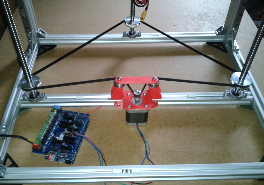
I am trying to come up with a simple design for a new printer. In this example the Y axis is driven by a single stepper with a common shaft to drive 2 outward pulleys. The thinking behind this is that it would eliminate any racking. the X axis would be typical belt drive with the motor moving with the carriage. Not sure the best approach for the Z axis/bed. Maybe a rod and lead screw at each corner with the screws being driven by a single belt. Anything wrong with this X,Y arrangement and suggestions on the Z axis? both images are the same. wasnt sure which would be more clear so I uploaded both
|
Re: thoughts on this design February 08, 2018 06:56PM |
Registered: 8 years ago Posts: 601 |
Sure, looks like a good arrangement. The Y axis motor may be in an awkward place though as it will impact on max travel distance of the XY gantry. It also means that both your pulleys and motor positions have to be very accurate in relation to each other otherwise the long connecting shaft will be bent. A similar solution would be to have the motor attached to the shaft with a small closed loop belt. This means only the pulleys must be accurately placed in relation to each other, and you can take advantage of easy gearing between motor and shaft.
Your XY gantry also has extra mass on it due to the x axis motor, have you considered coreXY? Not easy to implement compared to standard cartesian designs, but it has alot of advantages and not to be dismissed if you are designing a printer with a Z axis bed system.
Edited 1 time(s). Last edit at 02/08/2018 06:59PM by Origamib.
|
Re: thoughts on this design February 08, 2018 10:36PM |
Registered: 10 years ago Posts: 239 |
Thanks for the input. Good point on running a continuous shaft and small belt to the motor. I did want to maintain the 3:1 reduction I implemented on my current printer a couple years ago. That would take care of that and reduce the alignment challenges. Not too concerned with mass as the printer will be used for small nozzle work with high temp plastics and operate at slower speeds.
The next issue is how to move the bed up and down
The next issue is how to move the bed up and down
|
Re: thoughts on this design February 09, 2018 12:42AM |
Registered: 7 years ago Posts: 249 |
|
Re: thoughts on this design February 09, 2018 07:11AM |
Registered: 11 years ago Posts: 5,780 |
|
Re: thoughts on this design February 09, 2018 11:00AM |
Registered: 6 years ago Posts: 1,007 |
|
Re: thoughts on this design February 09, 2018 02:12PM |
Registered: 8 years ago Posts: 601 |
Quote
MKSA
You are half way to a Ultimaker. Keep going.
Why? Ultimaker has weight limitations that a standard axis does not. It also relies on the use of rods and bearings and the slop associated unless you buy quality
Standard cartesian designs have the advantage of easily adding extra tools, direct drive or even multiple X gantries
|
Re: thoughts on this design February 09, 2018 02:43PM |
Registered: 6 years ago Posts: 1,007 |
?Quote
Origamib
Quote
MKSA
You are half way to a Ultimaker. Keep going.
Why? Ultimaker has weight limitations that a standard axis does not. It also relies on the use of rods and bearings and the slop associated unless you buy quality
Standard cartesian designs have the advantage of easily adding extra tools, direct drive or even multiple X gantries
Compare the proposed design to the Ultimaker.
"A comical prototype doesn't mean a dumb idea is possible" (Thunderf00t)
|
Re: thoughts on this design February 09, 2018 07:41PM |
Registered: 10 years ago Posts: 239 |

|
Re: thoughts on this design February 10, 2018 11:05AM |
Registered: 11 years ago Posts: 5,780 |
The Cubex machines have a very heavy extruder carriage and a cantilevered bed. The extruders are crappy, but it you replace them with decent extruders, and put in a controller board that doesn't need proprietary filament cartridges, they can print well as long as you keep the print speed down to 30-40 mm/sec. Faster than that and the bed tends to bounce a lot. The XY stuff is OK (not great- I'm not fan of dual motors for anything), but I would not recommend a cantilevered bed for any but very small machines. 3 screws driven by 1 motor with two linear guides should provide a stable bed. A belt lifted Z axis is also possible if you build it right.
If you're going to try to print high temperature materials, you have to think about heating the enclosure and moving motors and electronics outside the enclosure. Belts are usually good to 85C, which is also about the maximum temperature for motors.
Ultra MegaMax Dominator 3D printer: [drmrehorst.blogspot.com]
|
Re: thoughts on this design February 10, 2018 02:57PM |
Registered: 10 years ago Posts: 239 |
Quote
the_digital_dentist
The Cubex machines have a very heavy extruder carriage and a cantilevered bed. The extruders are crappy, but it you replace them with decent extruders, and put in a controller board that doesn't need proprietary filament cartridges, they can print well as long as you keep the print speed down to 30-40 mm/sec. Faster than that and the bed tends to bounce a lot. The XY stuff is OK (not great- I'm not fan of dual motors for anything), but I would not recommend a cantilevered bed for any but very small machines. 3 screws driven by 1 motor with two linear guides should provide a stable bed. A belt lifted Z axis is also possible if you build it right.
If you're going to try to print high temperature materials, you have to think about heating the enclosure and moving motors and electronics outside the enclosure. Belts are usually good to 85C, which is also about the maximum temperature for motors.
I may have misstated slightly in that the Cube X design would be suitable. What I was thinking is that the XY arrangement looked suitable. What would be the drawback to the dual motors for the Y axis?
The heated chamber is definitely going to require a good bit of thought . We have a Fortus 400 (H-Bot) and 900 (conventional ball screw XY) at work so I have some "printing in an oven" examples to study. Strongly considering building 2 printers at the same time of similar design but one with the belts and rods and the other with ballcrews and linear slides. Welded square tube steel structure. I ultimately need 2 working printers. Belt driven will be dual E3D aquas (arriving any minute) and the ball screw version using 08-.1 nozzle extruders I have been working on for the last 2 years.
One thing that is tripping me up at the moment is the thermal barrier between the top of build chamber and the X.Y mechanics above. On the Fortus they use a fabric that is sewn, from a cross section view, in to a honeycomb shape that acts as an accordion to conform to the movement. Any ideas on what would be a suitable material to make this out of?
For the bed are you thinking 2 vertical mounted linear slides at the rear with a screw on either side with the 3rd screw towards the front?
|
Re: thoughts on this design February 10, 2018 05:18PM |
Registered: 8 years ago Posts: 601 |
What sort of temperatures are you hoping to achieve in your chamber? If it is for ABS, you will likely be happy with 40-60c and I don't think the fabric will be necessary unless you want to make the chamber heater very efficient. If you are aiming for 60c+, then it will be a nice touch as it will also have the added effect of keeping the mechanics cool so they don't bind at the higher temperatures.
As for material, I'm sure anything will be fine as long as it can be folded and it will withstand constant movement. Perhaps you could sew the folds and then use a relatively still material? It may also want to be fireproof in case it comes apart and comes into contact with your hot end.
As for material, I'm sure anything will be fine as long as it can be folded and it will withstand constant movement. Perhaps you could sew the folds and then use a relatively still material? It may also want to be fireproof in case it comes apart and comes into contact with your hot end.
|
Re: thoughts on this design February 10, 2018 06:41PM |
Registered: 11 years ago Posts: 5,780 |
Two screws and linear guides near the front on the sides and the third screw at the back. That makes it easy to take prints out from the front.
Dual motors don't necessarily stay in sync, especially if you use microstepping. That means you have to have some way to resynchronize the motors before printing otherwise the axes may not be orthogonal. If they get too far out of sync, they will bind. Prusa printers drive the X axis against the top of the frame which forces the screws to synchronize. I don't know if the original controller in the CubeX Duo did that- I think they were just relying on the noncompliance of the X axis to keep things synchronized. Your drawing arrangement is essentially identical to the Solidoodle printers XY mechanism.
Ultra MegaMax Dominator 3D printer: [drmrehorst.blogspot.com]
|
Re: thoughts on this design February 10, 2018 09:27PM |
Registered: 10 years ago Posts: 239 |
Quote
Origamib
What sort of temperatures are you hoping to achieve in your chamber? If it is for ABS, you will likely be happy with 40-60c and I don't think the fabric will be necessary unless you want to make the chamber heater very efficient. If you are aiming for 60c+, then it will be a nice touch as it will also have the added effect of keeping the mechanics cool so they don't bind at the higher temperatures.
As for material, I'm sure anything will be fine as long as it can be folded and it will withstand constant movement. Perhaps you could sew the folds and then use a relatively still material? It may also want to be fireproof in case it comes apart and comes into contact with your hot end.
200c or slightly above for the chamber temp printing PEI. As for the fabric you may very well be correct in thinking its nothing special. I may be forced to test here.
TDD, So maybe going back to a single shaft for the Y connected to both pulleys driven by a single motor or make provisions for both configurations and see whats best. I plan to go overkill with rigidity so any sync issues will probably not be absorbed well. Dah, the third screw in the front would make it impossible tho remove a print
|
Re: thoughts on this design February 10, 2018 11:37PM |
Registered: 10 years ago Posts: 239 |
TDD, since you've gone down the "printer from scratch" road a couple times would you mind offering some suggestions on linear slide size. Im targeting a build volume of 200x200x200, a print speed of 50-60 mm/s and 100 mm/s + rapids. The 2 E3d Aquas come in at close to 500 grams each and eat up 132mm side by side so the X will need about 350 mm of slide and a little less in Y. Im thinking 2 slides for the X axis with the extruders in between. The Y would obviously need 2 carrying the load of 2 extruders the X axis drive motor and the carriage.
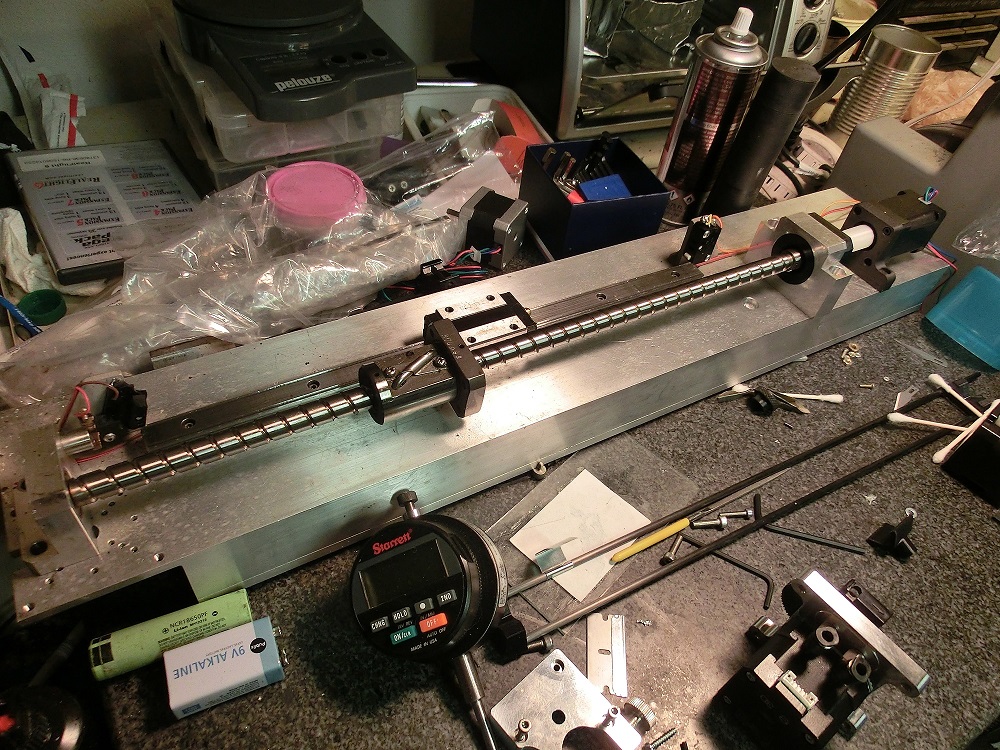
Also curious as to what the lead is on the ball screw you used for your SOM machine. You werent happy with the noise. I almost have my fixture ready to test different screw/ motor combos. The intent is to see what combination of motor step angle, motor size, screw lead and microstepping will give the best repeatability and accuracy along with quite operation using Duet electronics.
I started the topic off with belts. To avoid confusion the intent is to build 2 machines. One with screws and one with belts.
|
Re: thoughts on this design February 11, 2018 02:29AM |
Registered: 8 years ago Posts: 5,232 |
I don't get tired to post the 3 ballscrew arrangement for my CoreXY.
Two rails and one leadscrew in the back, the other leadscrews at the sides. Make sure the screws on the side are out off the printheads area, or it will eventually crash.
Two rails and one leadscrew in the back, the other leadscrews at the sides. Make sure the screws on the side are out off the printheads area, or it will eventually crash.
|
Re: thoughts on this design February 11, 2018 03:54AM |
Registered: 10 years ago Posts: 14,672 |
You can solve the issue of keeping Z motors in sync by driving the stepper motors from separate motor drivers, and then having the firmware use the Z probe to level the bed by adjusting the motors individually. When done with 3 leadscrews, this also means that you don't need manual bed leveling screws. The downside is that you need 6 stepper drivers, and with Duet electronics this involves the additional cost of a DueX2 expansion board, or lashing up a Pololu module to drive the extruder.
There is a published printer design (Railcore) that has options for either a single motor with belt/pulley drive to the 3 leadscrews or to use separate motors and drivers for them. The person who did the 3-motor conversion posted about it here [forum.seemecnc.com].
Either solution will work; which is better for you depends on whether you prefer to keep the mechanics simple at the cost of more expensive and complicated electronics, or vice versa.
Large delta printer [miscsolutions.wordpress.com], E3D tool changer, Robotdigg SCARA printer, Crane Quad and Ormerod
Disclosure: I design Duet electronics and work on RepRapFirmware, [duet3d.com].
|
Re: thoughts on this design February 11, 2018 09:17AM |
Registered: 11 years ago Posts: 5,780 |
Your lead screw looks a lot like the one I used. IRIC the pitch is 10mm. I used a 425 oz-in NEMA-23 motor and a DSP driver with a 32V power supply to move it. The motor can easily drive it at 80-90 mm/sec, but there is a nasty resonance at about 50 mm/sec that causes it to skip steps. That means I have to keep print and travel speed under 50 mm/sec in that printer, so I have set all the slicing profiles for it on the computers at the makerspace to 40mm/sec, where it delivers excellent print quality with no Y axis ringing and no layer shifting. I have tried numerous solutions to the resonance and can't get rid of it. I've tried ustepping all the way to 256:1 and it is still pretty noisy. I don't recall what ustepping it is set to right now, maybe 64:1. At 256:1 the speed would be limited to about 20mm/sec with that screw, but that's not interpolated 256:1. If I used a driver with interpolated ustepping it would work fine at higher speeds. I didn't notice any reduction in noise level beyond about 32:1.
I assume that you're planning to use linear guides. I don't think the size of the guide rails for the Y axis will matter as they'll be fully supported and 3D printers don't put much of a load on them. The main consideration is attaching the X axis rails to them, so larger bearing blocks can be convenient, but not necessary. You can always attach the X axis rails to metal plates and screw them to any size bearing block. If you're running two X axis guide rails, I would think that 12mm rails would be big enough for that span, but I don't have any means of simulating the dynamic behavior so I'm just guessing. My X axis is a single 24x8 mm rail and it works well with a single extruder on a span of about 380mm.
The Y axis rails are also 24x8mm and are gross overkill. I buy guides when I can get them cheaply. These were $80 for the pair IRIC. I recently picked up a pair of new 450 mm long, 12 mm THK linear guides for $68 on ebay. That's about what crappy HiWin knockoffs cost. That kind of deal shows up pretty regularly, you just have to wade through all the other stuff and use the advanced search options to find them.
If you're planning to heat things up to print ABS the frame expansion will move the Y axis rails apart. I used an extra bearing block on the X axis to allow that without creating huge side loads on the Y axis blocks/rails. That could be avoided by using a steel subframe for the XY stage, or somehow thermally isolating the frame from the heated build chamber.
Ultra MegaMax Dominator 3D printer: [drmrehorst.blogspot.com]
|
Re: thoughts on this design February 11, 2018 11:07AM |
Registered: 10 years ago Posts: 239 |
Thanks for time and all the valuable insight guys.
Yes TDD, The screw pictured is 10 mm lead (12 mm dia) . Im hoping through the use of DC42's electronics I can get out of the resonance zone by running real high steps/sec. Like 40,000 with the 10mm lead/.9 stepper/16x ms. Lots of theory at this point. I have a lot of work to do.
When you say 24x8mm for your rails do you mean 24mm wide by 8mm tall
|
Re: thoughts on this design February 11, 2018 12:21PM |
Registered: 11 years ago Posts: 5,780 |
Yeah, they're wide and flat. The X axis rail is mounted sideways. IRIC it's an IKO LWLF-24.
Ultra MegaMax Dominator 3D printer: [drmrehorst.blogspot.com]
Ultra MegaMax Dominator 3D printer: [drmrehorst.blogspot.com]
Sorry, only registered users may post in this forum.