Limit switch wiring question..
Posted by ampapa
|
Limit switch wiring question.. November 16, 2017 04:26PM |
Registered: 7 years ago Posts: 128 |
I purchased some inexpensive limit switches without identifying their status as to NO or NC so I'm trying to understand how to tell the difference?
While wiring up my DuetWifi I assumed the switches were NC switches but to my surprise they appear to be NO or did I mis-wire something?
The DuetWifi board has a green light for the +3.3v as can be seen in the image below and I think that is a good sign.
and from a wiring perspective I thought I wired them correctly, red = 3.3, black=gnd, green=signal.
Can someone explain how the word "pulls" is being used in the descriptions?
Did I make a mistake in wiring them or are they NO switches?
If they are NO, can I reverse them to be NC by switching the BLACK and RED lines?
Thanks.


While wiring up my DuetWifi I assumed the switches were NC switches but to my surprise they appear to be NO or did I mis-wire something?
The DuetWifi board has a green light for the +3.3v as can be seen in the image below and I think that is a good sign.

and from a wiring perspective I thought I wired them correctly, red = 3.3, black=gnd, green=signal.
Can someone explain how the word "pulls" is being used in the descriptions?
Endstop switch pulls signal from GND to +3.3v when triggered - Active High/NC

Endstop switch pulls signal from +3.3v to GND when triggered - Active Low/NO
Did I make a mistake in wiring them or are they NO switches?
If they are NO, can I reverse them to be NC by switching the BLACK and RED lines?
Thanks.
|
Re: Limit switch wiring question.. November 16, 2017 06:13PM |
Registered: 10 years ago Posts: 14,672 |
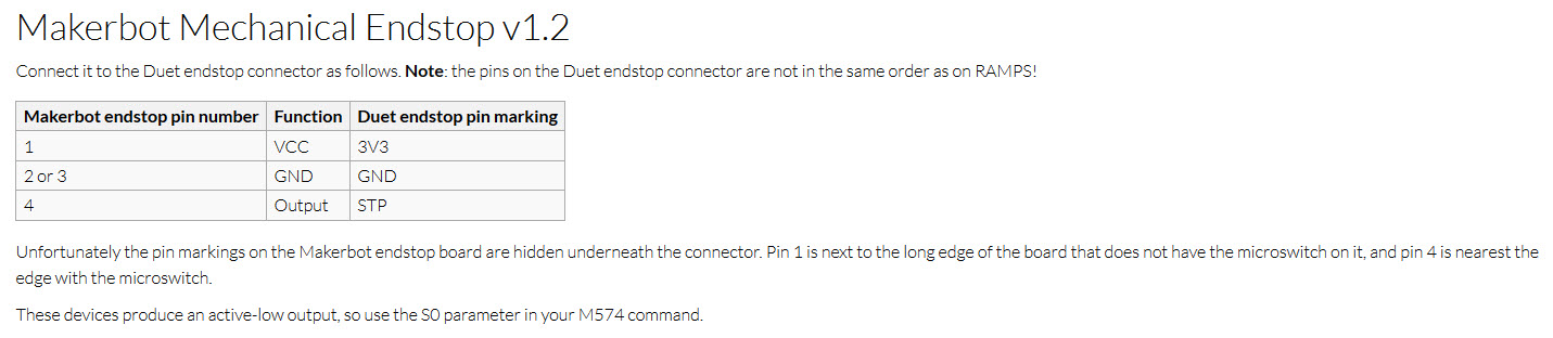
Those are not simple NO or NC microswitches. See "Makerbot mechanical endstop" in the Duet3D wiki page on connecting endstop switches.
Large delta printer [miscsolutions.wordpress.com], E3D tool changer, Robotdigg SCARA printer, Crane Quad and Ormerod
Disclosure: I design Duet electronics and work on RepRapFirmware, [duet3d.com].
Large delta printer [miscsolutions.wordpress.com], E3D tool changer, Robotdigg SCARA printer, Crane Quad and Ormerod
Disclosure: I design Duet electronics and work on RepRapFirmware, [duet3d.com].
|
Re: Limit switch wiring question.. November 16, 2017 07:18PM |
Registered: 8 years ago Posts: 3,525 |
I am almost certainly wrong but... in the description there:
Aren't the designations NC and NO here the wrong way around. A Normally Open switch reads 0v open and 3.3v closed and is active high. A normally closed switch reads 3.3v open and 0v closed and therefore is active low. NC fails-safe as a wire break causes the controller to read 0v, and stop rather than crash the axis.
Edited 2 time(s). Last edit at 11/16/2017 07:19PM by DjDemonD.
Simon Khoury
Co-founder of [www.precisionpiezo.co.uk] Accurate, repeatable, versatile Z-Probes
Published:Inventions
Endstop switch pulls signal from GND to +3.3v when triggered - Active High/NC

Endstop switch pulls signal from +3.3v to GND when triggered - Active Low/NO
Aren't the designations NC and NO here the wrong way around. A Normally Open switch reads 0v open and 3.3v closed and is active high. A normally closed switch reads 3.3v open and 0v closed and therefore is active low. NC fails-safe as a wire break causes the controller to read 0v, and stop rather than crash the axis.
Edited 2 time(s). Last edit at 11/16/2017 07:19PM by DjDemonD.
Simon Khoury
Co-founder of [www.precisionpiezo.co.uk] Accurate, repeatable, versatile Z-Probes
Published:Inventions
|
Re: Limit switch wiring question.. November 16, 2017 08:17PM |
Registered: 6 years ago Posts: 1,863 |
I am using one of these switches on my 3D Printer.
As the end stop board has a hardware 10K pull-up resistor added with the internal 4,7K pull-up you may want to disable pull-ups while using end-stop board.
I skipped this step as the current was not so high as to cause problems. If you have a limited supply you may want to enable individual end-stop pull-up resistors.
I have it coded as follows
#define X_MAX_ENDSTOP_INVERTING false // set to true to invert the logic of the endstop.
All other Endsotps are coded as follows
#define X_MIN_ENDSTOP_INVERTING true // set to true to invert the logic of the endstop.
#define Y_MIN_ENDSTOP_INVERTING true // set to true to invert the logic of the endstop.
using a proximity sensor for Z
#define Z_MIN_ENDSTOP_INVERTING false // set to true to invert the logic of the endstop.
Hope this helps
Edited 1 time(s). Last edit at 11/16/2017 08:45PM by Roberts_Clif.
|
Re: Limit switch wiring question.. November 16, 2017 08:44PM |
Registered: 7 years ago Posts: 128 |
Thanks DC42 for pointing me to the correct wiring.
Will re-wiring the switch effectively operate it as a NC switch which I understand is the better approach?
DjDemonD, that's what I'm seeing on the configuration tool description..
Edited 1 time(s). Last edit at 11/16/2017 08:45PM by ampapa.
Will re-wiring the switch effectively operate it as a NC switch which I understand is the better approach?
DjDemonD, that's what I'm seeing on the configuration tool description..
Edited 1 time(s). Last edit at 11/16/2017 08:45PM by ampapa.
|
Re: Limit switch wiring question.. November 17, 2017 02:05AM |
Registered: 8 years ago Posts: 3,525 |
When I've used these endstop boards on the past it has annoyed me that they work NO/active high and therefore have no failsafe mode. It sounds silly but it's easier to cut the switch off the pcb and just wire it from pin 1 to pin 3 which is a NC circuit.
Edited 1 time(s). Last edit at 11/17/2017 02:06AM by DjDemonD.
Simon Khoury
Co-founder of [www.precisionpiezo.co.uk] Accurate, repeatable, versatile Z-Probes
Published:Inventions
Edited 1 time(s). Last edit at 11/17/2017 02:06AM by DjDemonD.
Simon Khoury
Co-founder of [www.precisionpiezo.co.uk] Accurate, repeatable, versatile Z-Probes
Published:Inventions
|
Re: Limit switch wiring question.. November 17, 2017 03:23AM |
Registered: 10 years ago Posts: 14,672 |
Quote
DjDemonD
I am almost certainly wrong but... in the description there:
Endstop switch pulls signal from GND to +3.3v when triggered - Active High/NC

Endstop switch pulls signal from +3.3v to GND when triggered - Active Low/NO
Aren't the designations NC and NO here the wrong way around. A Normally Open switch reads 0v open and 3.3v closed and is active high. A normally closed switch reads 3.3v open and 0v closed and therefore is active low. NC fails-safe as a wire break causes the controller to read 0v, and stop rather than crash the axis.
The description is correct, because a microswitch with a 2-wire connection to the electronics pulls the input to 0V when it is closed, and the pullup resistor pulls the input to +3.3V when the switch is open.
Large delta printer [miscsolutions.wordpress.com], E3D tool changer, Robotdigg SCARA printer, Crane Quad and Ormerod
Disclosure: I design Duet electronics and work on RepRapFirmware, [duet3d.com].
Sorry, only registered users may post in this forum.