Precision Piezo Z-probe Now available.
Posted by DjDemonD
|
Re: Precision Piezo Z-probe Now available. February 13, 2018 04:33AM |
Registered: 8 years ago Posts: 487 |
Quote
o_lampe
I'm wondering why you didn't put the piezos in series?
You could put the piezo in series but there are some reasons why parallel is probably better; The wiring is simpler, you don't have to run a wire from one piezo to the other, just crimp the two piezos wires together at the connector. I'm going out on a limb here but, a piezo disk is a capacitor, if my understanding is correct the piezoelectric effect is a change in the capacitance of the ceramic due to applied strain (force). Adding capacitors in parallel adds their capacitance, adding them in series reduces the capacitance. If the change in capacitance and therefore the charge flow that we read is proportional to the total capacitance then by putting the disks in series we reduce the sensitivity, while by putting them in parallel we increase it. I'm not 100% confident of my reasoning here but I think I'm right, at least in part.
Idris
|
Re: Precision Piezo Z-probe Now available. February 13, 2018 10:50AM |
Registered: 6 years ago Posts: 35 |
I've been trying to move the heat sink above the effector plate to recover some height. I ran into an issue with sensitivity adjustments with the contraption I rigged up. The mechanical movements would cause a trigger, but turning down the sensitivity, nothing would trigger. Hopefully with the "Olampe Balanced Piezo" set up, I can finally get something working.
|
Re: Precision Piezo Z-probe Now available. February 13, 2018 11:33AM |
Registered: 8 years ago Posts: 3,525 |
Keen to hear how you get on, this might widen the scope quite a bit. On my corexy underbed, I am concerned since the bed moves in Z that its not just the noise but the inertia of the bed itself as the bed moves up to contact the nozzle, which pushes down on the underbed piezos, so noise-cancelling might not work but I will test it. I tried very low acceleration (and 0 jerk for Z during probing) which should limit the effect of inertia, so maybe noise was to blame.
Edited 1 time(s). Last edit at 02/13/2018 11:34AM by DjDemonD.
Simon Khoury
Co-founder of [www.precisionpiezo.co.uk] Accurate, repeatable, versatile Z-Probes
Published:Inventions
Edited 1 time(s). Last edit at 02/13/2018 11:34AM by DjDemonD.
Simon Khoury
Co-founder of [www.precisionpiezo.co.uk] Accurate, repeatable, versatile Z-Probes
Published:Inventions
|
Re: Precision Piezo Z-probe Now available. February 13, 2018 12:32PM |
Registered: 8 years ago Posts: 5,232 |
|
Re: Precision Piezo Z-probe Now available. February 13, 2018 07:47PM |
Registered: 6 years ago Posts: 54 |
I crimped 2 twenties and put them into an existing holder but was not able to confirm operation of the lower piezo. These were mounted brass to brass in parallel red,red blk,blk. Connected to a V1.22 board. Is a plunger needed on both sides?
Stef
As an afterthought perhaps 2 of Simon's singles glued back to back?
Edited 2 time(s). Last edit at 02/13/2018 08:48PM by Chowa.
Stef
As an afterthought perhaps 2 of Simon's singles glued back to back?
Edited 2 time(s). Last edit at 02/13/2018 08:48PM by Chowa.
|
Re: Precision Piezo Z-probe Now available. February 14, 2018 01:38AM |
Registered: 8 years ago Posts: 3,525 |
Hi Stef,
Just to be clear you don't want to place both Piezos as the sensor so putting two back to back into a bed mount will generate little/no noise but also no signal. As the piezo facing one way cancels the piezo facing the other way. Take one of the Piezos out of the mount and just bond it to the carriage nearby facing one way up, leave the other in the mount facing the other way. Now try it.
Sorry if I've misunderstood what you're trying, if so post a photo.
The idea is to create an equilibrium between the sensor piezo and the noise cancelling piezo during axis z movement, but to have a definite difference between them when the nozzle contacts.
Edited 1 time(s). Last edit at 02/14/2018 01:40AM by DjDemonD.
Simon Khoury
Co-founder of [www.precisionpiezo.co.uk] Accurate, repeatable, versatile Z-Probes
Published:Inventions
|
Re: Precision Piezo Z-probe Now available. February 14, 2018 12:38PM |
Registered: 6 years ago Posts: 54 |
|
Re: Precision Piezo Z-probe Now available. February 14, 2018 01:05PM |
Registered: 6 years ago Posts: 54 |
Folks:
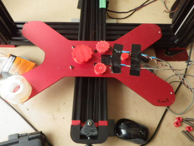
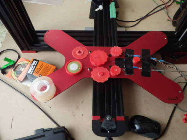
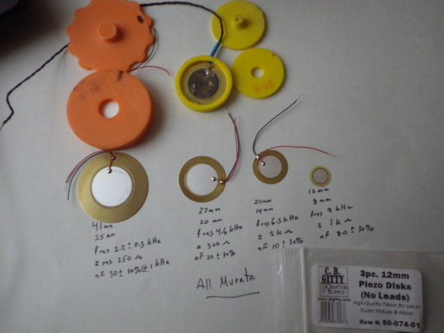
Here are some images of the underbed sensor array (different size piezos) for testing purposes. The range from 12mm, 20mm ,27mm and 41mm. The main difference besides the size is the resonant frequency and capacitance. I found it necessary to detune the larger piezos due to excessive noise pickup.
Here are several probing samples M48 and SD calculations. Note that these are only preliminary at this time.
Cold 27mm Tuned
1 Mean 0.161296
2 Min 0.158
3Max 0.164
4 Range 0.006
5 SD 0.001967
41mm Hot 135C 65CTuned M48 P20
1 0.007012
2 0.002
3 0.010
4 0.008
5 0.001983
I use only 1 piezo at a time. More to come
Stef
|
Re: Precision Piezo Z-probe Now available. February 14, 2018 02:23PM |
Registered: 8 years ago Posts: 3,525 |
Quote
Chowa
Simon
As I understand the second piezo is mounted to the carriage to act as a noise source(microphone) for the main signal and is 180 out of phase with the sensor signal thus providing a noise cancelling function.and it is not mounted touching the actual build plate?
Stef
Yes you need a second piezo (or Piezos if you have multiple sensor piezos) bond them to the carriage if using underbed. And yes out of phase by turning them over and wiring red to red or keeping them the same facing and wiring them black to red.
Edited 2 time(s). Last edit at 02/14/2018 02:57PM by DjDemonD.
Simon Khoury
Co-founder of [www.precisionpiezo.co.uk] Accurate, repeatable, versatile Z-Probes
Published:Inventions
|
Re: Precision Piezo Z-probe Now available. February 15, 2018 11:13AM |
Registered: 6 years ago Posts: 54 |
Here are the next set of numbers:
12mm twisted pair tuned (had to tune as o/p was low) Cold
m48 with anti phase 20mm piezo twisted pair on i/p 2
m48 m48 p20
1 0.024902 0.034095 0.011717 0.017700
2 0.024 0.029 0.007 0.017
3 0.027 0.042 0.014 0.019
4 0.003 0.013 0.006 0.002
5 0.001149 0.004105 0.001886 0.000694
1 = Mean, 2 =Min 3 = Max, 4 = Range 5= SD
The sensor mounts on build carriage see fotos my previous. Anti phase on carriage mount double side tape
The column
Stef
Edited 1 time(s). Last edit at 02/15/2018 11:21AM by Chowa.
|
Re: Precision Piezo Z-probe Now available. February 15, 2018 12:58PM |
Registered: 9 years ago Posts: 465 |

|
Re: Precision Piezo Z-probe Now available. February 15, 2018 06:11PM |
Registered: 8 years ago Posts: 3,525 |
Looks good great range and dev.
Here a useful stl a mount to fit a universal kit pcb to a Piezo20 unit. [www.thingiverse.com]
Simon Khoury
Co-founder of [www.precisionpiezo.co.uk] Accurate, repeatable, versatile Z-Probes
Published:Inventions
Here a useful stl a mount to fit a universal kit pcb to a Piezo20 unit. [www.thingiverse.com]
Simon Khoury
Co-founder of [www.precisionpiezo.co.uk] Accurate, repeatable, versatile Z-Probes
Published:Inventions
|
Re: Precision Piezo Z-probe Now available. February 16, 2018 02:39AM |
Registered: 8 years ago Posts: 5,232 |
I must admit, I haven't considered using the Piezo probe for my Compact Carrier Delta yet. Drilling a hole in a sensor was freaking me out... 
Now I see several 3-Piezo designs ( 4 piezos, if you count in my little improvement ) and I'm tempted to try that on my Cycloid-Magarm adapter.
The area I marked with the blue circles is not very big. Only 14mm between the former Traxxas joints. Is there a chance to fit the Piezos there? Would I need a fourth Piezo, where would I put it?

|
Re: Precision Piezo Z-probe Now available. February 16, 2018 03:23AM |
Registered: 8 years ago Posts: 3,525 |
Murata make 12mm Piezos we have used before. If you are going to noise cancel the question is where should I put the other three piezos? But adding an extra one, or slightly amplifying one will probably help. If the machine is not very mechanically noisy you might not need any noise cancelling.
Edited 2 time(s). Last edit at 02/16/2018 05:59AM by DjDemonD.
Simon Khoury
Co-founder of [www.precisionpiezo.co.uk] Accurate, repeatable, versatile Z-Probes
Published:Inventions
Edited 2 time(s). Last edit at 02/16/2018 05:59AM by DjDemonD.
Simon Khoury
Co-founder of [www.precisionpiezo.co.uk] Accurate, repeatable, versatile Z-Probes
Published:Inventions
|
Re: Precision Piezo Z-probe Now available. February 16, 2018 05:53AM |
Registered: 6 years ago Posts: 60 |
|
Re: Precision Piezo Z-probe Now available. February 16, 2018 06:03AM |
Registered: 8 years ago Posts: 3,525 |
Quote
whosrdaddy
Why not bond the piezos to the bed?
no drilling, less hassle
I think the only reason this approach was thought to be less than ideal, was that the piezos are affected by heat. It turns out not as much as we first thought. So I'd be keen to hear who has tried this, how hot do you run the bed, are you tuning with the bed fully heated, how sensitive is the system?
Simon Khoury
Co-founder of [www.precisionpiezo.co.uk] Accurate, repeatable, versatile Z-Probes
Published:Inventions
|
Re: Precision Piezo Z-probe Now available. February 16, 2018 06:46AM |
Registered: 6 years ago Posts: 60 |
|
Re: Precision Piezo Z-probe Now available. February 16, 2018 07:03AM |
Registered: 8 years ago Posts: 3,525 |
Yes I have underbed on the minidelta and it works great. Sorry if there is some confusion but I thought you were asking does it work just bonding the piezos to the bed. The noise cancellers (if needed) possibly. The "sensor" piezos probably not so well.
Simon Khoury
Co-founder of [www.precisionpiezo.co.uk] Accurate, repeatable, versatile Z-Probes
Published:Inventions
Simon Khoury
Co-founder of [www.precisionpiezo.co.uk] Accurate, repeatable, versatile Z-Probes
Published:Inventions
|
Re: Precision Piezo Z-probe Now available. February 18, 2018 05:53PM |
Registered: 6 years ago Posts: 4 |
I have a question about the output voltage when the piezo is triggered.
I've installed a Precision Piezo kit into my newly built Hypercube Evolution. It's running an MKS Sbase controller with Smoothieware. I initially hooked the output into the Zmin port which is running at 5v and successfully controlling the other endstops on the printer (optical type). I wasn't able to get the piezo endstop to register closed, despite the blue LED on the piezo board flashing when hit. I removed the Precision Piezo unit and hooked it up to my bench power supply and put the oscilloscope on the output. When fed with 5V supply, the output of the board was only showing around 3.1V when triggered. When fed with 3.3V input, the output drops to around 2.7V triggered.
Is this normal? My reading of the documentation indicates that it should be outputting around 5V when fed with 5V.
I've worked around the problem for the moment by hooking the piezo board output up to Pin1.23 on J8 and reconfiguring Smoothieware to use that pin as the Zmin. It does work in that mode.
What should the triggered output of the board be when fed with 5V?
Thanks,
|
Re: Precision Piezo Z-probe Now available. February 18, 2018 06:09PM |
Registered: 8 years ago Posts: 487 |
Are you using a PP20 board (single piezo connection) or a universal board (three piezo connections)?
The Universal v2 kit board is active low output, that means that when triggered the output drops to a logic low voltage, somewhere around 2v IIRC. The output pulse is very brief, around 0.3 seconds long, it's very unlikely that you will be able to see a triggered output with M119. If you need to check whether the firmware is registering triggers, turn VR2 so that the blue LED is lit and the red LED is not lit, then call M119, then re-tune the board for normal use. Pull ups need to be turned off for both piezo boards.
Idris
{Precision Piezo} Accurate, repeatable, versatile z-probe plus piezo discs, endstop cables, pt100, 50w heaters.
|
Re: Precision Piezo Z-probe Now available. February 18, 2018 09:20PM |
Registered: 6 years ago Posts: 4 |
Quote
Moriquendi
Are you using a PP20 board (single piezo connection) or a universal board (three piezo connections)?
The Universal v2 kit board is active low output, that means that when triggered the output drops to a logic low voltage, somewhere around 2v IIRC. The output pulse is very brief, around 0.3 seconds long, it's very unlikely that you will be able to see a triggered output with M119. If you need to check whether the firmware is registering triggers, turn VR2 so that the blue LED is lit and the red LED is not lit, then call M119, then re-tune the board for normal use. Pull ups need to be turned off for both piezo boards.
Idris
Hi Idris,
I'm using the PP20 board. When I had it hooked up on the bench power supply and the oscilloscope, I did adjust VR2 so I had the blue LED fully on and the board triggered so I could observe the output. That's when I found that the output voltage was only around 3.1V. I also tried it back on the MKS Sbase board with the pot adjusted so that the trigger was on, and still didn't get the Smoothie firmware to see the trigger, until I changed the input pin on the Sbase from Zmin to Pin1.23 and reconfigured Smoothie.
So, it could be that the MKS Sbase board is unable to see a logic high of 3.1V on the Zmin input but can on Pin1.23, or that the PP20 board is outputting too low a logic high voltage when fed with 5V, hence my question.
Thanks,
Phil
|
Re: Precision Piezo Z-probe Now available. February 19, 2018 04:12AM |
Registered: 8 years ago Posts: 487 |
Hi Phil,
It would appear that you've found an issue with the PP20 and the MKSbase, 3.1v should register as a logic high but perhaps there's more hysteresis on that pin or some form of protection that's interfering. I haven't used an MKSbase but I have been using a Smoothieboard for a couple of years and it doesn't have this issue.
Idris
{Precision Piezo} Accurate, repeatable, versatile z-probe plus piezo discs, endstop cables, pt100, 50w heaters.
|
Re: Precision Piezo Z-probe Now available. February 20, 2018 07:20AM |
Registered: 6 years ago Posts: 4 |
Quote
Moriquendi
Hi Phil,
It would appear that you've found an issue with the PP20 and the MKSbase, 3.1v should register as a logic high but perhaps there's more hysteresis on that pin or some form of protection that's interfering. I haven't used an MKSbase but I have been using a Smoothieboard for a couple of years and it doesn't have this issue.
Idris
Hi Idris,
I do have a workable solution at the moment using the alternate pin, but I was mainly curious as to what the expected output of the PP20 should be when fed with 5v. I have some 3.3 to 5v level shifter boards laying around, so I might try one of them on the output and see if the MKSbase will recognise it on the Zmin input.
Regards,
Phil
|
Re: Precision Piezo Z-probe Now available. February 20, 2018 08:03AM |
Registered: 8 years ago Posts: 487 |
In theory it should, however, the output current of the opamp is limited and it doesn't drive the voltage up as high as it should. It's a design error but since it's never caused a problem in the past I've not got around to changing it, I'll probably add an output transistor in a future revision.
Idris
{Precision Piezo} Accurate, repeatable, versatile z-probe plus piezo discs, endstop cables, pt100, 50w heaters.
Idris
{Precision Piezo} Accurate, repeatable, versatile z-probe plus piezo discs, endstop cables, pt100, 50w heaters.
|
Re: Precision Piezo Z-probe Now available. February 22, 2018 09:23AM |
Registered: 6 years ago Posts: 5 |
Hello everyone, i am writing here since i cannot really get this sorted oout:
I bought the Precision Piezo kit, and i am trying to install with 3 point underbed. Already printed all holders and connected to the MKS but i cannot make the piezo work as per instructions:
Setup:
FLSun Delta with MKS Board 1.0 running Marlin. Piezoboard V2 universal.
3 piezo disks connected to the piezo board and placed under the bed.
Piezo Board connected to Z Endstop connector on the MKS, measured voltage 3.3v, wired green connector to TRG on the piezo board.
Piezo board turns on, red led on, blue led on.
I tested the V1 and reads around 500k ohms, so it is good to go
Now for the problem:
When calibrating the V2 potentiometer the red light never goes off, while the blue light can be turned off, depending on setting
When both lights are on (blue+red), by touching the piezo i get the blue light flicker and go off
When calibrated to have the blue light off, it never goes on again by touching the piezos.
So, here it is already different from the provided instructions. How do i make the red go off and blue on and invert when touching the piezo?
On a second point, what do i have to change in Marlin to make it work? Has anyone a working guide for this (setting the type of sensor etc)?
Thank you !
|
Re: Precision Piezo Z-probe Now available. February 22, 2018 10:50AM |
Registered: 8 years ago Posts: 3,525 |
Hi so if the red light never turns off then something is amiss. Perhaps the piezo is faulty or has bad wiring? If you set it up on the bench just with 5v and GND connected, leave VR1 at 0.5Mohm that's fine, and one piezo connected, you should be able to get the red Led to come on and off with VR2. The point at which it just comes on is the most sensitive point. If this doesn't work then something is possibly faulty.
As for Marlin you would disable Pullup resistor for z min. Set logic to Inverted. Then test, if necessary invert the logic. You can set "pause before probing" and we would recommend 400ms minimum.
Simon Khoury
Co-founder of [www.precisionpiezo.co.uk] Accurate, repeatable, versatile Z-Probes
Published:Inventions
|
Re: Precision Piezo Z-probe Now available. February 22, 2018 12:12PM |
Registered: 6 years ago Posts: 60 |
|
Re: Precision Piezo Z-probe Now available. February 22, 2018 12:40PM |
Registered: 8 years ago Posts: 3,525 |
No on latest boards which are universal kit board v2 and Piezo20 v1.1 the red led is TRG. The TRG works normally closed. So the red Led is on and 5v/3.3v is present on the TRG pin until a trigger then the blue LED comes on for 0.25 seconds the TRG pin drops to closer to 0v. Then the board resets back to red being on.
If your system cannot be modified to accept active low/NC signal then you can on the universal kit board use SIG pin instead which works the same as 1.x boards.
Edited 1 time(s). Last edit at 02/22/2018 12:42PM by DjDemonD.
Simon Khoury
Co-founder of [www.precisionpiezo.co.uk] Accurate, repeatable, versatile Z-Probes
Published:Inventions
|
Re: Precision Piezo Z-probe Now available. February 22, 2018 01:38PM |
Registered: 9 years ago Posts: 465 |
Just ordered a generic underbed setup.
Very atypical for me, it's a "leap before you look" situation, so I haven't actually got an implementation plan, but I had thought that the underbed mount setup seemed more attractive to me. I'm looking forward to receiving my kit and working with it.
MBot3D Printer
MakerBot clone Kit from Amazon
Added heated bed.
Leadscrew self-built printer (in progress)
Duet Wifi, Precision Piezo parts
|
Re: Precision Piezo Z-probe Now available. February 22, 2018 02:46PM |
Registered: 8 years ago Posts: 34 |
Will you be releasing the schematic for the v2 board in the future? Only I have an embryo of a plan which is to design and make (well OshPark can actually make it for me) a single PCB for my HyperCube Evolution I'm currently building which would terminate all the various cables from the control board (Fans, Heater, Thermistor, X End Stops etc.) on the X carriage somewhere. And I'd also like to incorporate the piezo detection circuitry. I've seen something very similar on Thingiverse which gave me the idea.


Sorry, only registered users may post in this forum.