Pololu geared DC motor 30g prototype extruder
Posted by ipcalit
|
Pololu geared DC motor 30g prototype extruder May 07, 2016 10:59PM |
Registered: 7 years ago Posts: 78 |
Tagging along with the recent work on DC motor driven printers, here is an early attempt to get an ultralight extruder using readily available all-metal geared micromotors.
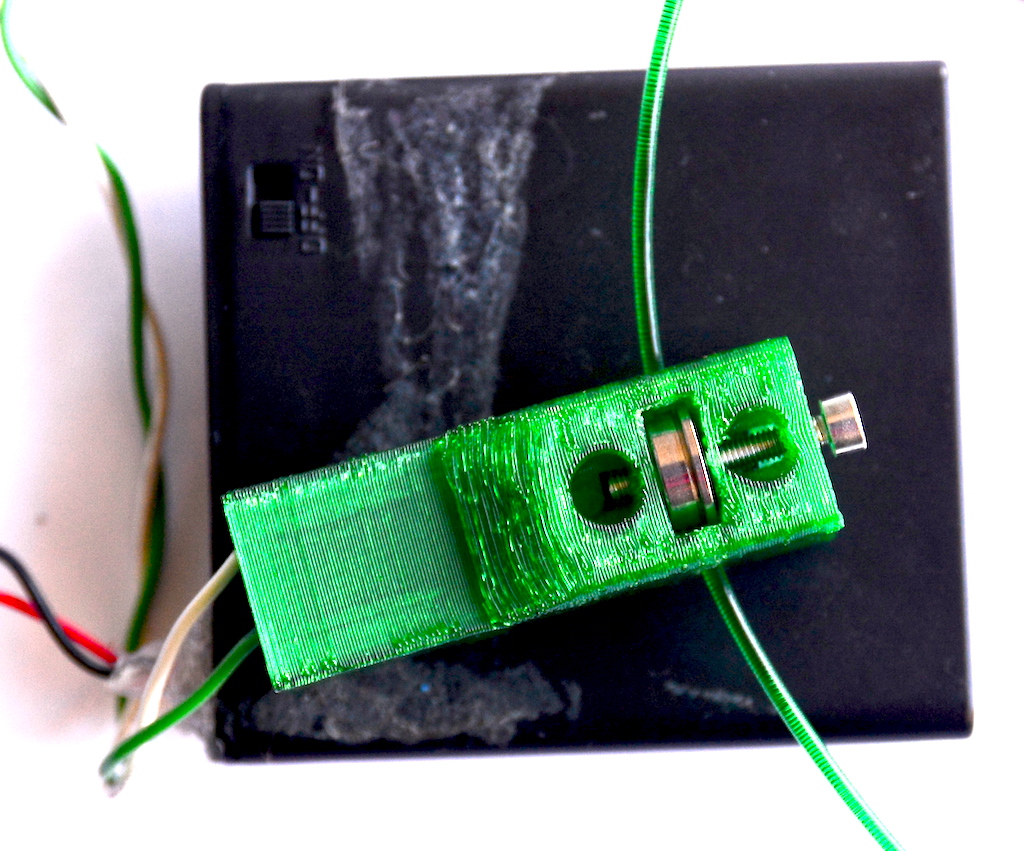
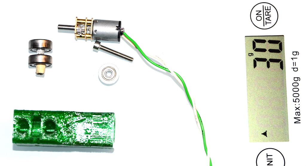
The entire package is currently 30g (including the printed housing). According to initial tests with a digital scale and rubber-band the setup can pull/push up to 2.7kg at 4.8V (4x 1.2 AA NiMH) with 1.75mm PETG before the filament starts to slip.
Paired with a E3Dv6 with 0.4mm nozzle it seems to have no problem pushing PETG at 245C in the air. No tests with it hooked up to the printer yet as it would need one of these magnetic encoders first: [www.pololu.com]
Parts:
- 2 x 624 bearings as supports for the knurled shaft
- 1 x 623 flanged bearing as idler
- 1 x M3 20mm screw
- 1 x 15mm aluminum pipe/spacer (4mm outer, 3.1mm inner) knurled with an M3 tap
- printed housing (tested with PETG)
- Pololu equivalent micro-gear DC motor (6V) 30rpm (also listed as FN20 size on alibaba and ebay, such as KM-12FN20)
[www.ebay.com]
If you have the parts and want to give it a try, first print the housing in PETG or PLA, then while your printer is busy make grooves into the aluminum pipe with the tap about 5mm from one end. Insert one 624 bearing through the other end of the pipe and then squeeze that end over the D shaft of the gearbox. After you get the housing, insert and push the motor with gearbox all the way down. The first 624 bearing should follow right past the "window" in the housing. Insert the other 624 bearing at the end to stabilize the shaft. Test the motor and make sure the pipe rotates within the bearing smoothly. If all OK, insert the 623 flanged bearing through the window with the flange towards the last 624 bearing. Slowly insert/thread the M3 screw in the slot between the housing and the outermost 624, then through the 623 and past it into the housing. Inserting the screw deeper adjusts the tension by using the housing as spring. Feed with filament and power from 4-9V.
|
Re: Pololu geared DC motor 30g prototype extruder May 08, 2016 11:16AM |
Registered: 8 years ago Posts: 181 |
|
Re: Pololu geared DC motor 30g prototype extruder May 08, 2016 11:43AM |
Registered: 11 years ago Posts: 31 |
|
Re: Pololu geared DC motor 30g prototype extruder May 08, 2016 12:21PM |
Registered: 7 years ago Posts: 78 |
The flanged bearing was used because it was available, but an interesting side-effect is that it prevents the bearing from squeezing the filament too much to flatten it.
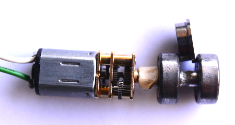
The shaft is a simple hollow aluminum spacer (a.k.a. pipe) that matches the outside diameter of the gearbox shaft and has 4mm on the outside. It should be available at most hardware stores as aluminum, copper, or brass.
An improvement would be to use 625 or 95-2Z bearings instead of the 624s to increase the shaft diameter to 5mm and use a proper steel shaft. I don't have a lathe, but 5mm bar stock could be knurled then drilled axially and with a set screw fixed on the motor shaft, similar with the Mk8 extruder gear. It would be much sturdier and grip stronger. If anybody wants to make one I'd like to see the results.
Edited 1 time(s). Last edit at 05/08/2016 12:34PM by ipcalit.
|
Re: Pololu geared DC motor 30g prototype extruder May 08, 2016 12:27PM |
Admin Registered: 13 years ago Posts: 730 |
Hi ipcalit, thanks for sharing this. I hope you keep us posted with how the project turns out.
If you don't already know this, you may be interested that many of the early RepRap designs did in fact use DC motors with encoders. Here are some (very) old links about extruder controllers using encoders:
MagServo
Extruder Controller 2.2
Magnetic Rotary Encoder v1.0
Nophead also did quite a bit of work with DC motor + encoder extruders:
DC gearmotor + encoder vs stepper (for extruder)
Even though people looked into this several years ago, many things are different today (especially the increased use of 1.75mm filament instead of 3mm) so maybe it is worthwhile investigating DC motor extruders again.
|
Re: Pololu geared DC motor 30g prototype extruder May 08, 2016 04:05PM |
Registered: 11 years ago Posts: 31 |
|
Re: Pololu geared DC motor 30g prototype extruder May 08, 2016 04:32PM |
Registered: 10 years ago Posts: 564 |
PID tuning is actually not that hard - most systems can be made to work OK over a wide range of PID values. I suspect "PID tuning is hard" is often just short hand for "understanding all the crap that goes into a servo control system is hard". There are definitely more things you need understand, but there's also an element of having a feel for what a properly functioning servo system should look like. In my many years doing customer support for servo control systems, this was often the main stumbling block in getting people up and running.
|
Re: Pololu geared DC motor 30g prototype extruder May 08, 2016 04:45PM |
Registered: 8 years ago Posts: 181 |
Check the code of Misan on github - he made a simple processing script, that can help you visualize the approach curve and tune PID using 6 keys.Quote
B4Me
Its kinda sadpid tuning is hard.. but then again, a good guide can help A LONG way !
I made a small adjustment (ability to store current values on keypress), but that's just nice-to-have.
This helped me to set working (I am not stating ideal here, ok?) PIDs for 5 motors already.
|
Re: Pololu geared DC motor 30g prototype extruder May 09, 2016 03:51PM |
Registered: 7 years ago Posts: 78 |
Another little known fact is that the LPC17xx micro-controller used by Smothieboard and its clones (such as Azteeg X5 mini) has a built-in hardware Quadrature Encoder Interface, which could save a lot of trouble with interfacing the proposed DC extruder.
The idea is to just hook-up the P1.20 to the A output of the encoder, P1.23 to B. The P1.24 Index to count revolutions is not available from the Pololu magnetic encoder.
[www.pololu.com]
If Arthur/ Roy/ nophead want to comment on this or check the schematics of the boards whether the pins are already out/accessible it would save us some time.
Some work is necessary on the firmware, probably writing a new extruder module, but there seems to be some QEI support already under /src/libs/LPC17xx/LPC17xxLib/src/lpc17xx_qei.c. Any takers?
|
Re: Pololu geared DC motor 30g prototype extruder May 14, 2016 04:06AM |
Registered: 8 years ago Posts: 5,232 |
I had second thoughts about the geared motors vs. direct drive.
To achieve the same amount of output torque the geared motor would have to turn faster and therefor would have the same inertia ( rotor mass x RPM ? )
So in theory the lower mass of the small rotor AND the friction of the gears would end up in a higher power consumption of the small motor.
Combine that with the smaller cooling surface of the small motor and problems are guaranteed.
This inertia problem occurs every time a motor starts or changes direction, which is pretty often...
Is my "math" correct or is rotor diameter also involved in the inertia equation? Then we would have to discuss small dia & long rotors vs. big dia & short rotors ( same motor weight )
Edited 1 time(s). Last edit at 05/14/2016 04:10AM by o_lampe.
|
Re: Pololu geared DC motor 30g prototype extruder May 14, 2016 06:28PM |
Registered: 7 years ago Posts: 78 |
Quote
o_lampe
I had second thoughts about the geared motors vs. direct drive.
To achieve the same amount of output torque the geared motor would have to turn faster and therefor would have the same inertia ( rotor mass x RPM ? )
So in theory the lower mass of the small rotor AND the friction of the gears would end up in a higher power consumption of the small motor.
Combine that with the smaller cooling surface of the small motor and problems are guaranteed.
This inertia problem occurs every time a motor starts or changes direction, which is pretty often...
Is my "math" correct or is rotor diameter also involved in the inertia equation? Then we would have to discuss small dia & long rotors vs. big dia & short rotors ( same motor weight )
Not sure if you got the scale of the thing, but the motor+gearbox is 2/3 of AA battery. All moving parts impact the inertia equation, just that their mass is probably 1/20 of a typical NEMA17 (complete motor+gearbox is mere 9g). During tests, the tiny motor seems to have no trouble stopping and reversing direction. In general, the extruder goes smoothly as most firmwares try to keep the pressure constant (important for Bowden). There are two exceptions: (1) layer change where it might have to stop (you can keep extruding in the infill with a smart slicer) (2) on retraction. I didn't notice any cooling issue yet but I didn't run it very long. Awaiting for encoder and perhaps insights into using QEI with Smoothieboard.
|
Re: Pololu geared DC motor 30g prototype extruder May 15, 2016 05:53AM |
Registered: 8 years ago Posts: 5,232 |
|
Re: Pololu geared DC motor 30g prototype extruder May 17, 2016 02:23AM |
Registered: 7 years ago Posts: 78 |
Quote
o_lampe
I know the size of your motor/gearbox, but the motor spins much faster then a direct driven DC motor.
I was surprised to see the motor completely inserted in the housing. Would it be enough to push only the gearbox in the ( shorted ) housing?
The motor probably has around 6000-7000rpm in contrast with the 60-100rpm of a direct drive. Yet, using ballpark figures and simplified calculations for inertia: 6g (rotor + gears) x 2mm (rotor radius) x 7000rpm < 150g (NEMA17 rotor) x 16mm (NEMA17 rotor radius) x 60rpm.
The initial design was fully enclosed to protect the motor and encoder from bumps/mishaps. The newer version has the motor almost completely exposed for cooling and weight reduction. I'll probably try with another one with less gearing (100rpm) to see if it makes any significant difference in achievable push force. For now the grip is probably the limiting factor.
|
Re: Pololu geared DC motor 30g prototype extruder May 17, 2016 02:43AM |
Registered: 8 years ago Posts: 181 |
Not that I'd like to disagree, but your calculation is a bit wrong - NEMA17 shaft radius is 2.5mm (5mm diameter). However, it can spin (tested) up to 4000rpm.
For me, the biggest problem here is the price of the motor+encoder - I've got 5 of the motors for $7, but with no encoder. And that seems to be the major difference here
I'll do my tests - if a simple hall-effect sensor on the outside of the motor housing will not be enough to measure something - I'd love to have the motor as an extruder drive, when playing with it on 12V, I am unable to even slow down the shaft by hand, unbelievable torque for such a small housing.
|
Re: Pololu geared DC motor 30g prototype extruder May 17, 2016 12:40PM |
Registered: 8 years ago Posts: 5,232 |
|
Re: Pololu geared DC motor 30g prototype extruder May 17, 2016 07:45PM |
Registered: 7 years ago Posts: 78 |
Quote
rklauco
Not that I'd like to disagree, but your calculation is a bit wrong - NEMA17 shaft radius is 2.5mm (5mm diameter). However, it can spin (tested) up to 4000rpm.
For me, the biggest problem here is the price of the motor+encoder - I've got 5 of the motors for $7, but with no encoder. And that seems to be the major difference here
I'll do my tests - if a simple hall-effect sensor on the outside of the motor housing will not be enough to measure something - I'd love to have the motor as an extruder drive, when playing with it on 12V, I am unable to even slow down the shaft by hand, unbelievable torque for such a small housing.
Regarding the calculations, I don't think it is OK to consider just the NEMA17 shaft diameter as the rotor inside the housing is pretty big (say 35mm dia), which is the main culprit (even ignoring the depth of the rotor). That's why large NEMAs have more inertia for the same stack depth than the smaller one. Just compare the spec sheet of a NEMA17 of 24mm with that of a NEMA14 of the same 24mm depth.
The hall-effect sensor should show something, but might not be enough. Perhaps a pair of them on opposite sides. The encoder + disk is about $4 (you get two of each from Pololu for $8) and you only need one even if the motor overheats and needs replacement. It is worth experimenting as they can be found even cheaper on Aliexpress.
The biggest issue would be interfacing with the controller and typical 8bit controllers might have a hard time counting the steps. I didn't hear anything yet from any Smoothieboard experts regarding the use of the hardware QEI feature of the LPC17xx.
|
Re: Pololu geared DC motor 30g prototype extruder May 17, 2016 07:55PM |
Registered: 8 years ago Posts: 181 |
|
Re: Pololu geared DC motor 30g prototype extruder May 18, 2016 12:27AM |
Registered: 8 years ago Posts: 29 |
Inertia moment:
J = 0.5 * m * R^2
Kinetic energy
E = 0.5 * J * w^2
Stepper:
R = 0.02 m
m = 0.26 kg
w = 100 rpm = 5 rad/c
J=0.000052
E=0.00065 J
Small DC:
R=0.005 m
m= 0.011 kg
w=10000 rpm=500 rad/c
J=0.00000014
E=0.0175 J
*(values are rough)
Small DC is more "inertial" then big stepper due to high speed.
Edited 1 time(s). Last edit at 05/18/2016 12:30AM by Andrey_SSh.
|
Re: Pololu geared DC motor 30g prototype extruder May 18, 2016 03:19AM |
Registered: 7 years ago Posts: 78 |
Quote
Andrey_SSh
Inertia moment:
J = 0.5 * m * R^2
Kinetic energy
E = 0.5 * J * w^2
Stepper:
R = 0.02 m
m = 0.26 kg
w = 100 rpm = 5 rad/c
J=0.000052
E=0.00065 J
Small DC:
R=0.005 m
m= 0.011 kg
w=10000 rpm=500 rad/c
J=0.00000014
E=0.0175 J
*(values are rough)
Small DC is more "inertial" then big stepper due to high speed.
According to the measurements from rklauco, the motor spins at 4000rpm. Rounding up to 5000 and using the rotor+gearbox mass of 6g, we have J = 0.000000075, and E = 0.00234375 J -- an order of magnitude smaller. Yet, none of these are remotely accurate as we did not account for the idler bearings and the filament elasticity and the pressure from the nozzle, etc. In practical terms, there are other factors that have a much bigger impact.
Another idea for encoder - using a rotary tool (aka Dremel) cut a small slit on the flat side of the motor, say 5mm x 1mm and place a pair of IR LED + sensor. The light would bounce in the rotor armature and give three pulses per rotation, which is enough given the high ratio of the gearbox.
|
Re: Pololu geared DC motor 30g prototype extruder May 18, 2016 03:52AM |
Registered: 8 years ago Posts: 181 |
It's a waste of time these calculations.
First of all, inertia only applies to moving objects.
Therefore you only have to account the weight of the rotor, not the stator part of the motor.
And, in the small DC, it's magnitudes smaller - like 2 orders of magnitude.
Also, the inertia by design applies to the shaft, BUT the shaft has a serious breaking force introduced by the gearbox right to it. Therefore the resistive force of the gearbox will significantly limit all the inertia moment from the shaft.
Simply said - the inertia of the small DC motor is so small, it's irrelevant for the usage in extruder in total - the weight of the hobbed shaft + relevant part of moving bearings is bigger then the motor.
I have a bit of an issue with the motor-to-shaft coupling. I am trying to come up with something different - like 5-to-3mm reduction and using directly MK7 gear. However, I do not have currently the needed material, so I'll be doing some shopping this afternoon.
While the IR sensor is probably possible, I don't want to drill into the motor. My other driving idea is to glue a magnet on top of the MK7 bolt and use something like the ASM sensor for magnetic rotation. Or I can still use another circular encoder wheels with huge resolution and quadrature encoder as I did for Z axis - there I have resolution of ~3000 impulses per 1mm of movement, that should be plenty for extruder
|
Re: Pololu geared DC motor 30g prototype extruder May 18, 2016 12:53PM |
Registered: 7 years ago Posts: 78 |
Quote
rklauco
I have a bit of an issue with the motor-to-shaft coupling. I am trying to come up with something different - like 5-to-3mm reduction and using directly MK7 gear. However, I do not have currently the needed material, so I'll be doing some shopping this afternoon.
I'm thinking along the same lines using stock 5mm brass/aluminum to make it easier for other to replicate, but I have the Mk8 gear that has a smaller diameter (6.7mm) and should provide about 35% increase in torque (there was a study about mk7 vs mk8).
Another possibility is to engage a larger rubber-coated wheel/gear in a similar way with the belt-driven designs that recently circulated. I don't like adding other wheels, but this could to drive the filament without compression (see attached). The drawback is a more complicated design and parts that are hard to source.
Quote
rklauco
While the IR sensor is probably possible, I don't want to drill into the motor. My other driving idea is to glue a magnet on top of the MK7 bolt and use something like the ASM sensor for magnetic rotation. Or I can still use another circular encoder wheels with huge resolution and quadrature encoder as I did for Z axis - there I have resolution of ~3000 impulses per 1mm of movement, that should be plenty for extruder
If you're thinking glue, then the gearbox could be removed from the motor (just two screws) and just glue a tiny magnet directly on top of the driving gear of the motor. Put it back together and use the space in the gearbox to get the sensor right next to that magnet. Alternatively glue a tiny piece of aluminum foil to act as mirror for IR sensor. You'll have one step per revolution.... or just buy the ready-made setup from Pololu and save yourself the trouble
|
Re: Pololu geared DC motor 30g prototype extruder May 18, 2016 01:18PM |
Registered: 8 years ago Posts: 181 |
Interesting - I've never seen drive like that. I have an idea how to use it, but...Quote
ipcalit
Another possibility is to engage a larger rubber-coated wheel/gear in a similar way with the belt-driven designs that recently circulated. I don't like adding other wheels, but this could to drive the filament without compression (see attached). The drawback is a more complicated design and parts that are hard to source.
First of all - the friction will be unpredictable - if there is just a small problem on the filament path, it will slip.
Second of all - I was previously using some cheaper PLAs that would break from time to time being bent in such a way. The drive gear would have to have serious diameter to compensate for that and I think that would remove to 30g tag from your thread name
Maybe I have a bit different motor, but on mine the distance from the shaft with the first wheel and the "first floor" of the gearbox is very (VERY) small - like 1mm tops. And half of the "free" area is taken by additional gear on the right side of the first wheel.Quote
ipcalit
If you're thinking glue, then the gearbox could be removed from the motor (just two screws) and just glue a tiny magnet directly on top of the driving gear of the motor. Put it back together and use the space in the gearbox to get the sensor right next to that magnet.
It's difficult to describe
And my phone cannot make macro picture
|
Re: Pololu geared DC motor 30g prototype extruder May 18, 2016 01:35PM |
Registered: 8 years ago Posts: 181 |
|
Re: Pololu geared DC motor 30g prototype extruder May 18, 2016 02:42PM |
Registered: 12 years ago Posts: 1,236 |
Quote
ipcalit
The biggest issue would be interfacing with the controller and typical 8bit controllers might have a hard time counting the steps. I didn't hear anything yet from any Smoothieboard experts regarding the use of the hardware QEI feature of the LPC17xx.
I had a look at the schematic here [smoothieware.org] and P1[20] is connected to LED3, and P1[23] is spare, both are routed to headers.
Might need to sacrifice an LED but it looks doable.
The cheap motors with encoders I bought off ebay turned out to be Mitsumi M28N-1, decent quality I think.
What is Open Source?
What is Open Source Hardware?
Open Source in a nutshell: the Four Freedoms
CC BY-NC is not an Open Source license
|
Re: Pololu geared DC motor 30g prototype extruder May 18, 2016 02:56PM |
Registered: 8 years ago Posts: 181 |
I'm not really sure I follow.Quote
bobc
I had a look at the schematic here [smoothieware.org] and P1[20] is connected to LED3, and P1[23] is spare, both are routed to headers.
Might need to sacrifice an LED but it looks doable.
As I see the capabilities of the chip, it can only read 1 encoder. You will need 2-4 (depends on which axes/extruder do you want to modify).
One quadrature encoder in HW will not help you much.
Am I mistaken?
Is there some dark magic how one can connect more than 1 encoder to the chip?
|
Re: Pololu geared DC motor 30g prototype extruder May 18, 2016 03:08PM |
Registered: 7 years ago Posts: 78 |
Here is an older attempt for a belt-driven extruder:Quote
rklauco
Interesting - I've never seen drive like that. I have an idea how to use it, but...Quote
ipcalit
Another possibility is to engage a larger rubber-coated wheel/gear in a similar way with the belt-driven designs that recently circulated. I don't like adding other wheels, but this could to drive the filament without compression (see attached). The drawback is a more complicated design and parts that are hard to source.
[0x7d.com]
There's another one more recent but I can't find the link. It has the belt going from the motor to two idlers arranged in an L pattern (motor at one end of L, idlers at the join and other end of L). The filament goes along the interior side of the L, between the outside of the belt and another large wheel (rubber or plastic). The belt and large wheel form a guide for the filament and the belt tension bends the filament to go around the large wheel.
Friction doesn't have to be predictable as you are engaging a long section of filament over a quarter of the wheel diameter. The PFTE tubing depicted in orange presses the filament against the wheel and guides/bends it along the way. The design is still very close to direct drive as you're not using the wheel to gain torque, just to gain grip.Quote
rklauco
First of all - the friction will be unpredictable - if there is just a small problem on the filament path, it will slip.
Second of all - I was previously using some cheaper PLAs that would break from time to time being bent in such a way. The drive gear would have to have serious diameter to compensate for that and I think that would remove to 30g tag from your thread name
To make it simple and keep the weight low, with this design you can get rid of two bearings (such as the 624s) and print a "hollow" wheel of a large diameter. A large rubberband or piece of GT2 belt could be glued to the wheel to provide traction. Attached is an 8T LEGO compatible gear for the motor and the matching 56T gear with an 80T GT2 pulley driver.
Quote
rklauco
Maybe I have a bit different motor, but on mine the distance from the shaft with the first wheel and the "first floor" of the gearbox is very (VERY) small - like 1mm tops. And half of the "free" area is taken by additional gear on the right side of the first wheel.Quote
ipcalit
If you're thinking glue, then the gearbox could be removed from the motor (just two screws) and just glue a tiny magnet directly on top of the driving gear of the motor. Put it back together and use the space in the gearbox to get the sensor right next to that magnet.
It's difficult to describe
There are many variations to the gearbox to accommodate multiple ratios. How about adding a transparent PET disk (from a soda bottle) that you color half black with permanent marker (Sharpie) under/over the driving gear (wherever it fits)? You would bounce the light from the IR LED from one side of the gearbox through the disk into the brass gear casing and receiving it on the other side with the sensor? The blacked-out section of the disk will prevent the bounce from happening/dim the light.
|
Re: Pololu geared DC motor 30g prototype extruder May 18, 2016 03:15PM |
Registered: 7 years ago Posts: 78 |
Quote
rklauco
I'm not really sure I follow.Quote
bobc
I had a look at the schematic here [smoothieware.org] and P1[20] is connected to LED3, and P1[23] is spare, both are routed to headers.
Might need to sacrifice an LED but it looks doable.
As I see the capabilities of the chip, it can only read 1 encoder. You will need 2-4 (depends on which axes/extruder do you want to modify).
One quadrature encoder in HW will not help you much.
Am I mistaken?
Is there some dark magic how one can connect more than 1 encoder to the chip?
For now even if we get just the DC motor extruder to work it would be of great benefit for most Delta and CoreXY machines or those with multiple nozzles. No more Bowden lag, and you get closed-loop feedback on the cheap.
If this works as expected, then we can think of boards with more encoders and going DC on all axes. The RepRap community would gain immensely from this experiment anyway.
Update: seems that popular 3d Doodler pens use a similar motor to drive the filament:
[www.flickr.com]
[talesofa3dprinter.blogspot.com]
[blog.banggood.com]
If anybody has one of these, it would be great to compare the diameter of the drive gear with the Mk7 or Mk8 commonly in use. Seems like a run-of-the-mill 18T gear, which could be replaced by one brass insert for M3 and some epoxy. No bearings are used on the shaft of the motor, which could lead to premature failure.
Edited 2 time(s). Last edit at 05/18/2016 04:50PM by ipcalit.
|
Re: Pololu geared DC motor 30g prototype extruder May 18, 2016 05:48PM |
Registered: 8 years ago Posts: 181 |
Wow, that could be interesting.Quote
ipcalit
If anybody has one of these, it would be great to compare the diameter of the drive gear with the Mk7 or Mk8 commonly in use. Seems like a run-of-the-mill 18T gear, which could be replaced by one brass insert for M3 and some epoxy. No bearings are used on the shaft of the motor, which could lead to premature failure.
I wonder how the plastic gears for the 90deg. turn work - I would expect them to wear out quickly. Maybe not so much on a pen, but on a printer working with much longer prints...
|
Re: Pololu geared DC motor 30g prototype extruder May 18, 2016 06:40PM |
Registered: 8 years ago Posts: 181 |
Well, this was fun.
I identified 3rd gear in the gearbox that would be a potential candidate for any sort of optical tracking - it's located at an accessible part of the gearbox and has some room above it.
So, I tried to hook up additional TB6612 and tried to drive it slowly so I can see if how fast does the gear spin comparing to the output shaft.
Let's say not all went according to plan.
I have no idea what mistake I did, but I burned 2 TB6612 drivers - their capacitors blew directly upon connecting 12V.
I switched to L298N then and tested, but I lost 2 drivers - and I have no idea why.
I have exactly the same circuit on my right driving X, Y and Z axis of my DC-driven printer no problem. I used the same wiring and even similar Arduino code for this...
I'd call it a bad night.
|
Re: Pololu geared DC motor 30g prototype extruder May 19, 2016 12:00AM |
Registered: 7 years ago Posts: 78 |
Quote
rklauco
Wow, that could be interesting.Quote
ipcalit
If anybody has one of these, it would be great to compare the diameter of the drive gear with the Mk7 or Mk8 commonly in use. Seems like a run-of-the-mill 18T gear, which could be replaced by one brass insert for M3 and some epoxy. No bearings are used on the shaft of the motor, which could lead to premature failure.
I wonder how the plastic gears for the 90deg. turn work - I would expect them to wear out quickly. Maybe not so much on a pen, but on a printer working with much longer prints...
Somebody took the v2 pen apart and it uses the same motor, just this time with a screw drive like the very early Repraps. It inherits the rotating filament issue, which means you need to feed it straight pieces of filament.
[www.disruptivemagazine.com]

Sorry, only registered users may post in this forum.