ljc18a3-h-z/bx
Posted by Swengson
|
ljc18a3-h-z/bx November 18, 2015 05:59AM |
Registered: 8 years ago Posts: 29 |
Hello all,
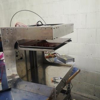
I build my own 3d printer.
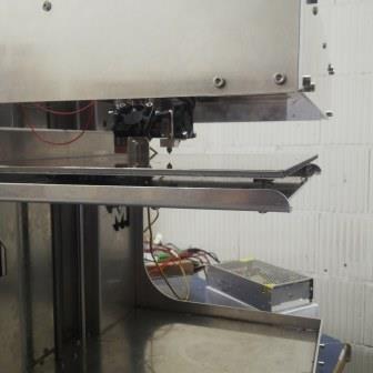
I want to use auto leveling. I have a capacitive sensor.
Everything looks alright. The sensor is connect to the motherboard (megatronics V3.0)
When the sensor detect something he gives a light.
So everything looks alright. but when I home the Z-axes and I detect the Z-axes he don't stop....
When i do i with my opto sensor. that is the sensor before the auto leveling sensor. he works very good...
See the pictures for the sensor and my printer
thank you
I build my own 3d printer.
I want to use auto leveling. I have a capacitive sensor.
Everything looks alright. The sensor is connect to the motherboard (megatronics V3.0)
When the sensor detect something he gives a light.
So everything looks alright. but when I home the Z-axes and I detect the Z-axes he don't stop....
When i do i with my opto sensor. that is the sensor before the auto leveling sensor. he works very good...
See the pictures for the sensor and my printer
thank you
|
Re: ljc18a3-h-z/bx November 18, 2015 02:35PM |
Registered: 9 years ago Posts: 978 |
|
Re: ljc18a3-h-z/bx November 19, 2015 02:19AM |
Registered: 8 years ago Posts: 29 |
|
Re: ljc18a3-h-z/bx November 19, 2015 11:45AM |
Registered: 8 years ago Posts: 3,525 |
Check your sensor by connecting + and - to 12v and 0v.
If it is a pnp sensor place volt meter on 0v and signal. The signal should be 12v when the sensor is open then change to 0v when it comes near an object. This is normally closed (NC).
You need to supply the printer with a 5v signal (on ramps at least) so use a voltage regulator to achieve this. Voltage dividers ie. Resistors are not as reliable and wasteful of power and will heat up. A voltage regulator is very cheap.
If it is an npn sensor then attach 12v and 0v then place voltmeter between 0v and signal, if it is working then the voltage changes from 0v to 12v when triggered. This is normally open (NO). Again use a voltage regulator to drop the signal voltage to 5v.
If the sensor works then the issue is wiring or that you're not connecting it to the right pin on ramps. The pins are 5v,0v and signal going from inside to outside on the board. Make sure it is the z min endstop you are connected to. The 5v is not normally enough to power the sensor, it will work with some sensors the led might not work, so connect the sensor to 12v from the power supply.
Depending on the sensor type you'll have to set endstop logic to true or false, just try both and see which one works properly ie open when open and triggered when an object is close usually within 3mm. I enable endstop pull up in firmware but I'm not sure it needs to be.
Edited 2 time(s). Last edit at 11/19/2015 02:10PM by DjDemonD.
|
Re: ljc18a3-h-z/bx November 22, 2015 11:17AM |
Registered: 8 years ago Posts: 29 |
|
Re: ljc18a3-h-z/bx November 23, 2015 11:22AM |
Registered: 8 years ago Posts: 3,525 |
You can specify either 3 point levelling which is enough assuming your bed is flat.
Or you can specify 4 points or 9 points.
This is the auto levelling section from my config.
I've highlighted the area in red where you set the probing points so set it to 2 if you want 4 points probed i.e. a 2x2 grid or 3 if you want 9 points probed a 3x3 grid.
comment this out if you prefer a 3 point probing system which is fine as long as your bed is flat.
You need to define the probing grid carefully - my settings are for a 200mm x200mm bed with a probe offset as in the are highlighted in green.
The probing grid values can be negative. It depends on the offset of your sensor from the nozzle.
You can change the z offset up or down depending on how high/low your nozzle is after autolevelling.
#define ENABLE_AUTO_BED_LEVELING // Delete the comment to enable (remove // at the start of the line)
#define Z_PROBE_REPEATABILITY_TEST // If not commented out, Z-Probe Repeatability test will be included if Auto Bed Leveling is Enabled.
#ifdef ENABLE_AUTO_BED_LEVELING
// There are 2 different ways to pick the X and Y locations to probe:
// - "grid" mode
// Probe every point in a rectangular grid
// You must specify the rectangle, and the density of sample points
// This mode is preferred because there are more measurements.
// It used to be called ACCURATE_BED_LEVELING but "grid" is more descriptive
// - "3-point" mode
// Probe 3 arbitrary points on the bed (that aren't colinear)
// You must specify the X & Y coordinates of all 3 points
#define AUTO_BED_LEVELING_GRID
// with AUTO_BED_LEVELING_GRID, the bed is sampled in a
// AUTO_BED_LEVELING_GRID_POINTSxAUTO_BED_LEVELING_GRID_POINTS grid
// and least squares solution is calculated
// Note: this feature occupies 10'206 byte
#ifdef AUTO_BED_LEVELING_GRID
// set the rectangle in which to probe - note left position is absolute coordinates of probe so left is left etc..
#define LEFT_PROBE_BED_POSITION 5
#define RIGHT_PROBE_BED_POSITION 143
#define BACK_PROBE_BED_POSITION 170
#define FRONT_PROBE_BED_POSITION 5
// set the number of grid points per dimension
// I wouldn't see a reason to go above 3 (=9 probing points on the bed)
#define AUTO_BED_LEVELING_GRID_POINTS 3
#else // not AUTO_BED_LEVELING_GRID
// with no grid, just probe 3 arbitrary points. A simple cross-product
// is used to esimate the plane of the print bed
#define ABL_PROBE_PT_1_X 15
#define ABL_PROBE_PT_1_Y 180
#define ABL_PROBE_PT_2_X 15
#define ABL_PROBE_PT_2_Y 20
#define ABL_PROBE_PT_3_X 170
#define ABL_PROBE_PT_3_Y 20
#endif // AUTO_BED_LEVELING_GRID
// these are the offsets to the probe relative to the extruder tip (Hotend - Probe)
// X and Y offsets must be integers
#define X_PROBE_OFFSET_FROM_EXTRUDER -45
#define Y_PROBE_OFFSET_FROM_EXTRUDER -20
#define Z_PROBE_OFFSET_FROM_EXTRUDER -2.2
#define Z_RAISE_BEFORE_HOMING 2 // (in mm) Raise Z before homing (G28) for Probe Clearance.
// Be sure you have this distance over your Z_MAX_POS in case
#define XY_TRAVEL_SPEED 8000 // X and Y axis travel speed between probes, in mm/min
#define Z_RAISE_BEFORE_PROBING 3 //How much the extruder will be raised before traveling to the first probing point.
#define Z_RAISE_BETWEEN_PROBINGS 3 //How much the extruder will be raised when traveling from between next probing points
//#define Z_PROBE_SLED // turn on if you have a z-probe mounted on a sled like those designed by Charles Bell
//#define SLED_DOCKING_OFFSET 5 // the extra distance the X axis must travel to pickup the sled. 0 should be fine but you can push it further if you'd like.
//If defined, the Probe servo will be turned on only during movement and then turned off to avoid jerk
//The value is the delay to turn the servo off after powered on - depends on the servo speed; 300ms is good value, but you can try lower it.
// You MUST HAVE the SERVO_ENDSTOPS defined to use here a value higher than zero otherwise your code will not compile.
// #define PROBE_SERVO_DEACTIVATION_DELAY 300
//If you have enabled the Bed Auto Leveling and are using the same Z Probe for Z Homing,
//it is highly recommended you let this Z_SAFE_HOMING enabled!!!
#define Z_SAFE_HOMING // This feature is meant to avoid Z homing with probe outside the bed area.
// When defined, it will:
// - Allow Z homing only after X and Y homing AND stepper drivers still enabled
// - If stepper drivers timeout, it will need X and Y homing again before Z homing
// - Position the probe in a defined XY point before Z Homing when homing all axis (G28)
// - Block Z homing only when the probe is outside bed area.
#ifdef Z_SAFE_HOMING
#define Z_SAFE_HOMING_X_POINT (X_MAX_LENGTH/2) // X point for Z homing when homing all axis (G28)
#define Z_SAFE_HOMING_Y_POINT (Y_MAX_LENGTH/2) // Y point for Z homing when homing all axis (G28)
#endif
#ifdef AUTO_BED_LEVELING_GRID // Check if Probe_Offset * Grid Points is greater than Probing Range
#if X_PROBE_OFFSET_FROM_EXTRUDER < 0
#if (-(X_PROBE_OFFSET_FROM_EXTRUDER * AUTO_BED_LEVELING_GRID_POINTS) >= (RIGHT_PROBE_BED_POSITION - LEFT_PROBE_BED_POSITION))
#error "The X axis probing range is not enough to fit all the points defined in AUTO_BED_LEVELING_GRID_POINTS"
#endif
#else
#if ((X_PROBE_OFFSET_FROM_EXTRUDER * AUTO_BED_LEVELING_GRID_POINTS) >= (RIGHT_PROBE_BED_POSITION - LEFT_PROBE_BED_POSITION))
#error "The X axis probing range is not enough to fit all the points defined in AUTO_BED_LEVELING_GRID_POINTS"
#endif
#endif
#if Y_PROBE_OFFSET_FROM_EXTRUDER < 0
#if (-(Y_PROBE_OFFSET_FROM_EXTRUDER * AUTO_BED_LEVELING_GRID_POINTS) >= (BACK_PROBE_BED_POSITION - FRONT_PROBE_BED_POSITION))
#error "The Y axis probing range is not enough to fit all the points defined in AUTO_BED_LEVELING_GRID_POINTS"
#endif
#else
#if ((Y_PROBE_OFFSET_FROM_EXTRUDER * AUTO_BED_LEVELING_GRID_POINTS) >= (BACK_PROBE_BED_POSITION - FRONT_PROBE_BED_POSITION))
#error "The Y axis probing range is not enough to fit all the points defined in AUTO_BED_LEVELING_GRID_POINTS"
#endif
#endif
#endif
#endif // ENABLE_AUTO_BED_LEVELING
Edited 1 time(s). Last edit at 11/23/2015 11:22AM by DjDemonD.
|
Re: ljc18a3-h-z/bx November 24, 2015 09:26AM |
Registered: 8 years ago Posts: 29 |
Sorry, only registered users may post in this forum.