Quick All Metal Rebuild Hot End
Posted by bstott
|
Quick All Metal Rebuild Hot End March 10, 2014 01:06AM |
Registered: 13 years ago Posts: 27 |
What do you do when money is short and catastrophy hits your 3D printer?
BUILD YOUR OWN PARTS --- OF COURSE!
About two weeks ago - End of Feb. 2014 - I was externally motivated to build/rebuild my hot end. Motivated by two things:
1) A component breaks. Some parts are just bad.
Hint: the threads are supposed to be attached to the aluminum riser.
AND
2) Motivated from a slipped out thermistor having created a Hot, Bubbling, Smoking, PEEK Melt Down!!!!
----->>>> After this event, My hot end was now ---- NOT a Hot End!!!
Factoid: Per Wikipedia -- PEEK "...melts around 343 °C (662 °F)..."
Note: The green part is ABS. Look how close to the heat. No melt. No distortion. Wow!
Well, after sitting stunned and airing out the house to the great outdoors, which was about -11°C (12°F) and snowing at the time, I began to do what most of us do ---> Think, more.
To build/re-build my new hot end from bits I needed something I had or cheap and readily purchased nearby. Off to the aisles of the local big box home supply store.
I have attached some build photos, for your viewing experience:
Individual components for a New Rebuild mostly metal hot end w/SS delivery.
Assembled New Rebuilt hot end.
Hot end mounted on Rostock effector.
[Note: Hot End requires active cooling from a fan. Copper seen in photo is passive material mostly for attachment and Cool! rather than cooling. ]
Components
- 1.5" X 1/8" SS Nipple (New purchase.)
- Alumninum Heatsink (Had in my piles: TO-220 size)
- Alumninum Heater Block (Remnant from old Hot End.)
- 0.40mm Brass nozzle (Remnant from old Hot End.)
- Aluminum mounting clamp-washer (Remnant repurposed from broken riser on old Hot End.)
- SS Push-to-connect 4mmOD/2mmID fitting (New purchased item for bowden tube.)
- PTFE delivery tube (Not Shown.) --- I was not able to get away from the PTFE. (PTFE is cheap and to remove it required too much work to go without.) (New purchase.)
I am now getting familiar with and using this new hot end. It heats up quickly and seems to have a good flow rate but, with a 0.40mm nozzle, it can not consistently extrude faster than 450mm of filament per minute. This hot end clears jams fast AND also jams fast if the fan is not turned on. LOL.
Factoid: 450mm of ~1.8mm dia filament equates to ~9.1 meters of extruded filament. Or over 29 feet.
Two implimention issues I've had so far.
- Plastic Leakage - Some ABS leakage due to ??? -- Hopefully a loose joint. Or my sloppy thread making. I only noticed on Saturday (3/9/14) it began a slow but, consistant ooze.
- Jamming - Two jams so far. These were due to user error and were quickly cleared by turning the cooling fan on, reversing the filament then, beginning to extrude again.
Jamming Cause
The plastic jamming was caused by the hot end fan not being turned on when the hot end was heating. This was my fault with misconfigured cooling gcode. The hot end fan, attached to the heatsink, was being turned off during printing at which point the entire hot end gets very hot, very fast. This too hot - hot end caused the plastic to swell and jam. But, as I wrote earlier --- The jamming was quickly cleared by turning on the fan, reversing the filament out then, extruding again. Very quick and easy. No worries (?). The plastic jam/blockage was cleared so quick I never had the chance to really sweat over a tear down.
All Metal Hot Ends ----
As you would figure - This type of hot end MUST be actively cooled at all times. Even though the Stainless Steel delivery is a poor conductor of heat - IT IS METAL and does get HOT! Fortunately, with a fan, the Aluminum Heat Sink works GREAT to cool the delivery zone QUICK! I haven't checked the upper end running temperatures but, without the fan, the upper end, at the push-to-connect fitting, gets too hot to touch. Soon after turning on the fan the same top end is comfortable to touch. And IT prints.
Hope this gives some ideas, encouragement, or entertainment. What will you do next?
Best to you all,
Brian.
Pittsburgh, PA
BUILD YOUR OWN PARTS --- OF COURSE!
About two weeks ago - End of Feb. 2014 - I was externally motivated to build/rebuild my hot end. Motivated by two things:
1) A component breaks. Some parts are just bad.

Hint: the threads are supposed to be attached to the aluminum riser.
AND
2) Motivated from a slipped out thermistor having created a Hot, Bubbling, Smoking, PEEK Melt Down!!!!
----->>>> After this event, My hot end was now ---- NOT a Hot End!!!
Factoid: Per Wikipedia -- PEEK "...melts around 343 °C (662 °F)..."


Note: The green part is ABS. Look how close to the heat. No melt. No distortion. Wow!
Well, after sitting stunned and airing out the house to the great outdoors, which was about -11°C (12°F) and snowing at the time, I began to do what most of us do ---> Think, more.
To build/re-build my new hot end from bits I needed something I had or cheap and readily purchased nearby. Off to the aisles of the local big box home supply store.
I have attached some build photos, for your viewing experience:
Individual components for a New Rebuild mostly metal hot end w/SS delivery.

Assembled New Rebuilt hot end.

Hot end mounted on Rostock effector.
[Note: Hot End requires active cooling from a fan. Copper seen in photo is passive material mostly for attachment and Cool!
rather than cooling. ]
Components
- 1.5" X 1/8" SS Nipple (New purchase.)
- Alumninum Heatsink (Had in my piles: TO-220 size)
- Alumninum Heater Block (Remnant from old Hot End.)
- 0.40mm Brass nozzle (Remnant from old Hot End.)
- Aluminum mounting clamp-washer (Remnant repurposed from broken riser on old Hot End.)
- SS Push-to-connect 4mmOD/2mmID fitting (New purchased item for bowden tube.)
- PTFE delivery tube (Not Shown.) --- I was not able to get away from the PTFE. (PTFE is cheap and to remove it required too much work to go without.) (New purchase.)
I am now getting familiar with and using this new hot end. It heats up quickly and seems to have a good flow rate but, with a 0.40mm nozzle, it can not consistently extrude faster than 450mm of filament per minute. This hot end clears jams fast AND also jams fast if the fan is not turned on. LOL.
Factoid: 450mm of ~1.8mm dia filament equates to ~9.1 meters of extruded filament. Or over 29 feet.
Two implimention issues I've had so far.
- Plastic Leakage - Some ABS leakage due to ??? -- Hopefully a loose joint. Or my sloppy thread making. I only noticed on Saturday (3/9/14) it began a slow but, consistant ooze.
- Jamming - Two jams so far. These were due to user error and were quickly cleared by turning the cooling fan on, reversing the filament then, beginning to extrude again.
Jamming Cause
The plastic jamming was caused by the hot end fan not being turned on when the hot end was heating. This was my fault with misconfigured cooling gcode. The hot end fan, attached to the heatsink, was being turned off during printing at which point the entire hot end gets very hot, very fast. This too hot - hot end caused the plastic to swell and jam. But, as I wrote earlier --- The jamming was quickly cleared by turning on the fan, reversing the filament out then, extruding again. Very quick and easy. No worries (?). The plastic jam/blockage was cleared so quick I never had the chance to really sweat over a tear down.
All Metal Hot Ends ----
As you would figure - This type of hot end MUST be actively cooled at all times. Even though the Stainless Steel delivery is a poor conductor of heat - IT IS METAL and does get HOT! Fortunately, with a fan, the Aluminum Heat Sink works GREAT to cool the delivery zone QUICK! I haven't checked the upper end running temperatures but, without the fan, the upper end, at the push-to-connect fitting, gets too hot to touch. Soon after turning on the fan the same top end is comfortable to touch. And IT prints.
Hope this gives some ideas, encouragement, or entertainment. What will you do next?
Best to you all,
Brian.
Pittsburgh, PA
|
Re: Quick All Metal Rebuild Hot End March 10, 2014 01:48AM |
Registered: 11 years ago Posts: 246 |

|
Re: Quick All Metal Rebuild Hot End March 10, 2014 02:42AM |
Registered: 10 years ago Posts: 1,381 |
I would like to see you conduct a simple test, if it's not too much of a bother. 
First test:
Take the aluminum heat sink off, and allow the fan to freely blow air past the SS barrel to see if you obtain the same performance.
Second test:
Duct the air flow to the SS barrel with some aluminum foil, and again without the aluminum heat sink.
Tks.
First test:
Take the aluminum heat sink off, and allow the fan to freely blow air past the SS barrel to see if you obtain the same performance.
Second test:
Duct the air flow to the SS barrel with some aluminum foil, and again without the aluminum heat sink.
Tks.
|
Re: Quick All Metal Rebuild Hot End March 10, 2014 03:28PM |
Registered: 13 years ago Posts: 27 |
@A2
Testing ---- Ha, ha.... after the catastrophy and the build I am not up to just tinkering. I'm not actually interested in developing this component but, to design and print of other objects. I want to use the machine not design machines.
A2: For your test - You say to duct air using aluminum foil? Foil on fan and not on SS? Purpose of this? Aluminum conducts heat - nothing hot touching then only ambient air temp. If blowing from room then only a channel. Neglibible heat dissipation assistance based on area and mass? I do not know?
My quesses about removing the heatsink? Probably good performance until the heat propagates up the SS tubing. The heatsink provides a lot of surface area along the length of the SS - probably more a detriment transfering heat from the heated block than an aid. But, with a fan - it prints. Auminum with its highly thermal conductive nature against a not so highly conductive material - I see your possible point that I may be initiating a problem of heating the riser.
Questions?
* Is the heatsink drawing the heat up the SS tubing? Quessed Answer: Probably.
* Would this design be better as with regpye's to have the heatsink smaller and further from the hot end? Quessed Answer: Probably
* Without the heatsink will the heat not travel up the tubing as readily and the hot end be able to print? Quessed Answer: Probably. But, for how long? Heat propagates with time. My MakerBot T-O-M has a SS heater block and riser with a very small heat sink and generally no fan. In time it gets hot and swells the plastic. But, I have printed for over three hours without active cooling. So - how long could I print with an aluminum heater block, stainless steel riser and a small aluminum heatsink without a fan? At least three hours?
Possible Conclusion: You are probably right that I crippled my hot end with the large heatsink and should mimic what regpye and the original T-O-M of three years ago had done. SS riser then small alumminum heatsink far from hot end. But,, for now my hotend is built and it prints.
Quessed Suggestion to others - keep a distance between the heater block and heatsink. The heatsink will then be smaller, further from heat source not drawing heat up the riser and would not require the active cooling from a fan. Seems to work for regpye.regpye posted picts.
Others design? heat block(metal), riser (SS), small remote heatsink (alum.) - Maybe or maybe not a small fan.
Quote
I would like to see you conduct a simple test, if it's not too much of a bother. smoking smiley
Testing ---- Ha, ha.... after the catastrophy and the build I am not up to just tinkering. I'm not actually interested in developing this component but, to design and print of other objects. I want to use the machine not design machines.
A2: For your test - You say to duct air using aluminum foil? Foil on fan and not on SS? Purpose of this? Aluminum conducts heat - nothing hot touching then only ambient air temp. If blowing from room then only a channel. Neglibible heat dissipation assistance based on area and mass? I do not know?
My quesses about removing the heatsink? Probably good performance until the heat propagates up the SS tubing. The heatsink provides a lot of surface area along the length of the SS - probably more a detriment transfering heat from the heated block than an aid. But, with a fan - it prints. Auminum with its highly thermal conductive nature against a not so highly conductive material - I see your possible point that I may be initiating a problem of heating the riser.
Questions?
* Is the heatsink drawing the heat up the SS tubing? Quessed Answer: Probably.
* Would this design be better as with regpye's to have the heatsink smaller and further from the hot end? Quessed Answer: Probably
* Without the heatsink will the heat not travel up the tubing as readily and the hot end be able to print? Quessed Answer: Probably. But, for how long? Heat propagates with time. My MakerBot T-O-M has a SS heater block and riser with a very small heat sink and generally no fan. In time it gets hot and swells the plastic. But, I have printed for over three hours without active cooling. So - how long could I print with an aluminum heater block, stainless steel riser and a small aluminum heatsink without a fan? At least three hours?
Possible Conclusion: You are probably right that I crippled my hot end with the large heatsink and should mimic what regpye and the original T-O-M of three years ago had done. SS riser then small alumminum heatsink far from hot end. But,, for now my hotend is built and it prints.
Quessed Suggestion to others - keep a distance between the heater block and heatsink. The heatsink will then be smaller, further from heat source not drawing heat up the riser and would not require the active cooling from a fan. Seems to work for regpye.regpye posted picts.
Others design? heat block(metal), riser (SS), small remote heatsink (alum.) - Maybe or maybe not a small fan.
|
Re: Quick All Metal Rebuild Hot End March 10, 2014 10:02PM |
Registered: 10 years ago Posts: 1,381 |
Quote
bstott
You say to duct air using aluminum foil? Foil on fan and not on SS? Purpose of this?
It's a guide.
Use card board if you don't have aluminum foil to duct the air from the fan directly onto the SS barrel.
Quote
bstott
Questions?
* Is the heatsink drawing the heat up the SS tubing? Quessed Answer: Probably.
No.
With or without the aluminum heat sink, the heat will diffuse throughout the SS barrel, until removed by another system, and brought into equilibrium.
As the heat moves up the barrel it's being redirected into the aluminum (path of least resistance) which reduces the temperature inside the barrel.
The mass and geometry of the heat sink aids in diffusing the heat to another part of that system.
So the more efficient that the heat sink is at removing the heat near the heater block the lower the temperature at the top of the SS barrel.
Quote
bstott
* Would this design be better as with regpye's to have the heatsink smaller and further from the hot end? Quessed Answer: Probably
Smaller heat sink: depends on specifically what geometry of the heat sink you are referring too.
For example there are formulas to calculate the thickness of the fins, the base, and surface area.
Located further away: where you locate the heat sink is where you begin redirecting the diffusion of the heat moving up the SS barrel.
The location of the heat sink will have some effect on the location, and size of the melt, and glass transition zones.
Quote
bstott
* Without the heatsink will the heat not travel up the tubing as readily and the hot end be able to print? Quessed Answer: Probably.
No the heat will travel up through the SS barrel at the same rate with or without the heat sink.,
But where the SS barrel is in contact with the aluminum heat sink, heat will be redirected into a material where the speed of diffusion is faster.
But if the heat sink is designed in a manner to restrict air flow, it might not be that effective.
Additionally if the heat sink is not swagged tightly to the SS barrel, and the heat has to traverse an air gap, it's efficiency it greatly reduced.
Quote
bstott
Possible Conclusion: You are probably right that I crippled my hot end with the large heatsink and should mimic what regpye and the original T-O-M of three years ago had done
You won't know unless you conduct a few simple test.
Quote
bstott
So - how long could I print with an aluminum heater block, stainless steel riser and a small aluminum heatsink without a fan?
That can be calculated, and modeled, but when it comes to gauging the efficiency of a heat sink, nothing beats an empirical test.
Too many variables to account for. That's why I would like to see you conduct the simple test I outlined.
Quote
bstott
Quessed Suggestion to others - keep a distance between the heater block and heatsink. The heatsink will then be smaller, further from heat source not drawing heat up the riser and would not require the active cooling from a fan
Without the heat sink you increase the melt, and glass transition zone.
Leaving a gap between the heater block and heat sink to increase the melt pool,
might be required to keep up with the rate of resin being extruded.
But it also could cause problems with jamming, because you increased the glass transition zone.
Heat sinkQuote
If there is no air flow around the heat sink, energy cannot be transferred.
Natural convection requires free flow of air over the heat sink.
If fins are not aligned vertically, or if fins are too close together to allow sufficient air flow between them,
the efficiency of the heat sink will decline.
[en.wikipedia.org]
I like one design feature of the heat sink you have, and it's probably better than most designs.
What I like, and what you don't see in the ones that you can purchase is the wide gaps between the fins, and amount of surface area.
You are using an engineered heat sink, but it's not being applied correctly.
Heat sinks need air flow.
Look at all the heat sinks that were designed by engineers, you will see that the air can freely move between thin fins, and they have a lot of surface area.
If the fins are close together the air if buffered from entering deep into the channels, and to the base of the heat sink where it's the hottest.
This is where I think most hot ends miss an easy opportunity to improve their efficiency.
Your heat sink even though it's applied incorrectly has nice wide gaps to allow the air to flow past, and a lot of surface area.
To improve your implementation, make sure the heat sink fins are tightly swagged to the SS barrel;
and drill some holes through the base of the heat sink to allow the air to pass through it.
The way you have it now the air is hitting a wall and buffeting fresh air from flowing past the fins.
The one feature that you can't improve is the Spreading resistance, because you don't have a heat sink base touching the SS barrel.
You only have the cross section of the fins touching the SS barrel, so that sets up a phenomenon called spreading resistance.
Are the fins swagged tightly to the SS barrel?
If it's not, then removing it might not have any noticeable effect, and a simple ducting/guidance of the air flow onto a naked SS barrel is all that you need.
When I say tightly swagged, I mean to the point you stress the heat sink to the point of near fracturing.
If it's easy to remove the heat sink, they it's not tight enough.
Before assembly you can polish the SS barrel to help bring more surface area in contact with the heat sink.
To help with assembly, and to fill in any tiny air gaps, apply anti-seize to the SS barrel, (if you don't mind it smoking for awhile).
So out of curiosity, I'm interested in your hot end design, and how well it would perform without the heat sink, and with a fan, will it be the same or worse.
Does ducted air onto the SS barrel equate to the same performance with marginal fin contact, and buffeted air.
A feature that I haven't seen on a hot end without a fan is vertically aligned fins.
Horizontal fins block hot air from naturally moving up.
Vertical fins pose a lot of design challenges for a hot end, that utilize a fan.
HTH
|
Re: Quick All Metal Rebuild Hot End March 10, 2014 11:53PM |
Registered: 13 years ago Posts: 27 |
@A2
Thanks for your inputs. I'll address this time without cut and paste --- I'm tired today.
What may not be apparent from my implimentation of a MOSFET heatsink is:
- The SS tubing is centered within the fins. This allows air clearance 360° around the riser. The benefit, or not, is that there is air flow all around the riser and the backstop of the heatsink will allow more air forced around the heatsink from the fan's output. This small part of assembly was thought about. Otherwise I'd have pulled out the dremel. As you noted the fins are too big and the back is too large too. In Heat Transfer class I'd finished a manual (by hand) calculus analysis of cooling fins and was remembering that their effectiveness dimishes over length. Thus, in designing components you try to maximize efficiencies and not to waste material or use too much space. Here all was neglible. The Heatsink was less than $1.00 when purchased sometime ago. The SS riser was ? $0.67+ $1.27 shipping. And the overall assembly size is all relatively small and fits fine on my machine.
- Swaging? No swaging. Too much damage. The heatsink was drilled and reamed to be interference fit (press fit) with the SS riser. The two parts were hydraulic pressed together. You are likely right about it having benifitted to have smoothed and polished the SS riser specifically at the mating of the heatsink but, considering the application I feel the benefit to be negligible. There would have been much more cooling surface area lost on the riser by smoothing its entire surface and too hard to polish only the fin mating spots. As is - The soft aluminum heatsink press fit against the hard SS riser will possibly conform the heatsink to the imperfect surface of the riser. If true, this will microscopically increase the mating surface area between the two parts but, negligible to over all heat transfer benefits. Just easier for production. In this application the rough cast SS piping surface also contributes a larger amount of external cooling surface area to the riser than a smooth rod. Good for my active cooling? Oh, I cheated in my build by going to a local machine shop for the assembly of the riser and heatsink. In test - Me and my hand drill destroyed one heatsink. LOL. I used to have tools. Now, it is - hand drill, dremel, child's hammer, a few hex keys, pliers and some screw drivers.
- Air flow? - The air flow idea for this build was to be forced air. So, with this application it works very well with the small fan. [CFM? Grabbed fan from scraps. It was small and worked. - Good Enough.] You are right the design is not correct but, works. If for a passive application it would be better to design vertical fins rather than horizontal?
- Heat Flow? ---- As you state - The heat flows to least resistance. Since the heatsink is full length of the SS riser it will contribute to the draw of heat from the heater block up the riser surface? and out the fins. The analysis would be interesting to see how much assistance, without the fan, the heatsink contributes to propogating the heat up the transistion zone. I would like a thermal image to see but, no such equipment. And, without the fan, the backstop of the heatsink will trap air to heat rather than cool. Negligible? Or not? You wrote about heatsink placement - yeah - since no math is being done here and no computer analysis there is only guess and hope. As I'd shared in an earlier post, the hot end will readily jam without the fan. But, then, just as rapidly cool and unjam once the fan is applied. That is OK. For now. Your questions for testing are good if I were to design to produce.
Say, since the parts are cheap and easy to assemble - If you do not have to involve a paid machinist - you are availed to some good simple experiments.
In my desire to build/re-build an inexpensive hot end - I am embarrassed to say - The extra parts were inexpensive but, I lost a couple weeks in the mail. Originally, I did not find what I wanted at the local DIY and chose to buy online. Then, not having any decent drill press, I paid a local machinist to drill and ream the heatsink and press fit the two parts. Result? I would have been better to calculate the likely trials of this rebuild and simply bought a J-Head instead. But, then, I'd have lost out the total experience, my own hot end component/assembly AND our sharing. Maybe I am better off with the hard route?
|
Re: Quick All Metal Rebuild Hot End March 11, 2014 12:51AM |
Registered: 10 years ago Posts: 22 |
Some silver heat sink epoxy might be easier than swaging the heatsink. The other easy way to do it if you have boreing or reaming tools is to make the hole in the heatsink a little smaller than the diameter of the stainless tube then press them together while the heatsink is heated up up to expand the hole.
|
Re: Quick All Metal Rebuild Hot End March 11, 2014 01:18AM |
Registered: 10 years ago Posts: 1,381 |
Quote
bstott
The heatsink was drilled and reamed to be interference fit (press fit) with the SS riser. The two parts were hydraulic pressed together.
Sounds like you know what you're doing

Quote
bstott
Air flow? - The air flow idea for this build was to be forced air.
Another thought, the fan will have more of an effect if it's parked right on top of the heat sink, just don't melt it.
Quote
bstott
In this application the rough cast SS piping surface also contributes a larger amount of external cooling surface area to the riser than a smooth rod. Good for my active cooling?
It would be difficult to measure the difference in temp drop, but in theory it's an improvement.
Quote
bstott
was remembering that their effectiveness dimishes over length
Correct
[sound.westhost.com]Quote
If the heatsink is made double the width, the thermal resistance is halved as you would expect
However, should you decide to make the heatsink twice as long, the thermal resistance is
reduced by the inverse of the square root of the increase - in this case 1 / √2 (0.707).
To get half the thermal resistance, the heatsink would need to be 4 times longer.
Quote
bstott
If for a passive application it would be better to design vertical fins rather than horizontal?
Correct, the air won't be able to convect up easily, and becomes stagnant with horizontal fins, and no fan.
Quote
bstott
the backstop of the heatsink will trap air to heat rather than cool. Negligible?
Ideally you want the air to orthogonally bombard the surface this creates more turbulence (heat exchange), not longitudinally flow past it.
The backstop creates a buffer, and reduces the average temp drop.
I don't think it's adding much to your system, place your hand on it and see how hot it is.
If it's marginally warm, then pop a few holes in it to let the air pass through, if it's hot, it's working.
Quote
bstott
- Heat Flow? ---- As you state - The heat flows to least resistance. Since the heatsink is full length of the SS riser it will contribute to the draw of heat from the heater block up the riser surface? and out the fins.
You don't have one heat sink, you have 4 mini heat sinks, with a lot of SS surface area exposed.
That's why I was curious if you could get away with no heat sink.
I was also making the assumption that you had a rough surface oversize drilled hole, but you don't.
SS doesn't give up heat as well as aluminum, and air is an insulator.
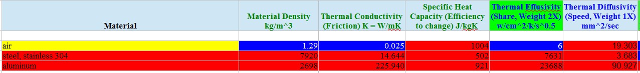
Look at the Thermal Effusivity values to see the huge differences between the three.

If you could cover the whole surface of the SS barrel with aluminum you will significantly improve the heat transfer vs. exposed SS.
I was also going to suggest a test of just press fitting an aluminum tube over the SS barrel to see if that was as effective as your present heat sink.
Only because you have four small heat sinks with a small surface area in contact with the SS barrel.
It would be pretty neat if all you needed was a cheap aluminum tube pressed over the hot end + a fan.
I think you did a great job with off the shelf parts!
Edited 1 time(s). Last edit at 03/11/2014 01:18AM by A2.
|
Re: Quick All Metal Rebuild Hot End March 11, 2014 08:47PM |
Registered: 13 years ago Posts: 27 |
|
Re: Quick All Metal Rebuild Hot End March 11, 2014 11:18PM |
Registered: 13 years ago Posts: 27 |

|
Re: Quick All Metal Rebuild Hot End March 12, 2014 06:26PM |
Registered: 13 years ago Posts: 27 |
disclaimer: I have not built this as a passive unit and it was not intended to be such.
@Svdharma
Silver heat sink epoxy? Does it withstand 300°C? What about the cost and sourcing? Is it cheap and easy to get in small quantities?
@A2
Fan placement:
The fan is within 5mm directly in front of the open fins and blows towards the solid back. This allows full 360° airflow around the SS riser.
Air is an insulator:
Air is only an insulator if captured and/or still. It has a high capacity to remove heat. That is why aircooled engines on motorcycles, automobiles, and airplanes work so well.
Vertical Fins:
Vertical fins on a passive hot end can be seen if you search and seek out the early MakerBot Thing-O-Matic MK5/MK6 hotends. They had a small circular aluminum heatsink with vertical fins slipped over their SS riser. The hot end has a SS heating block heated with two 5Ohm 5W resistors. It worked quite well. IF, you built it as they instructed. But, note that years ago we were not printing for 3 hours plus at a time and back to back. So, this passive cooled style of hot end worked for our, then, very long one hour prints.
Four heatsinks:
You state I do not have ONE heat sink but, Four mini heat sinks - TRUE and NOT. TRUE because what is attached to the riser is four individual pieces of aluminum. NOT because my heatsink is a system and connected at one end of the fins. As a passive unit it does not work well because of the horizontal fin orientations and the air is trapped and acts as an insolator but, my idea was always active and thus it works extremely well. The backstop assures that air circulates on all sides of the SS. But, remember this was a hack. I thought some simple science and grabbed some 'should work' parts. It does work - I think --- The brass nozzle shank burst today. HA< HA --- CRAPPY DESIGN ON SEEMECNC's HOT END. It has now suffered a broken riser from their faulty design and a bubbling PEEK thermal barrier because the Thermistor slipped out (A tiny bit my fault. But, would not have happend if I didn't have to keep screwing with SeeMeCNC's breaking parts.) And now their brass nozzle bursting!
Heat Transfer through materials
As to permeabiliy, capacity, effusivity, conductivity of the individual materials. Air - not relevent unless still or captured. If my fan is working this is irrelevent. SS does not take into account time which ALL the items will heat because heat does permeate through the materials. Unless removed at a higher rate than input. Aluminum, still requires some air movement. Now, Nophead, years ago, found out that heat propogates upwards via convection, conduction and radiation on the hot ends. He believes more convection upward to be a big contributor. So, he insolated his hot end to stop the melt zone extending up his riser causing jammings. This is simple heat transfer known for many ??? years, decades, centuries??? Anyway.
A point you haven't touched on yet is mounting. The reason your hot glue gun works and the soldering iron in hand with passive cooling works so well is that they have particular mounting styles. I have been curious to explore this but, I'm not currently going to change the mount on my printer. Maybe the next design but, not now. So, A passive all metal hot end at 180°C to 230°C plus is not likely to work now that we print for many hours, 3 to 12 plus hours, at a time. We need active cooling. Plus, active cooling introduces control and with control - reliability and repeatability. Both required for consistency of time spent and quality of product produced.
But, there are plenty of designs which will be very good for first stage consumer products because as a consumer and having a life - people won't be spending 3 to 12 + hours on the whole for printing things. They will be printing kitties, puppies, butterflies, toy cars, spoons, Christmas ornaments and things. Those take about an hour or so.
Stainless Steel Heat dissipation
The following points will be true:
- Disregarding comparing the conductivity of various materials, all items can easily be cooled with flowing air cooler than the item and the ambient air.
- Increasing the surface area of an item increases the capacity to cool the item.
With the above two points the rough surfaced SS riser in my hacked hot end gets good cooling from a fan. Likely with the fan I use and the riser it may not require a heatsink but, I did not do the math to verify and I am not keeping a intended pre-heat zone temperature. My intent is cold plastic into hot end. I look to a melt zone of no more than the thickness of the heat block which is approximately 10mm which may be too large but, that is the measurement of the block. A hack too. ;-)
Here is another tid bit. The heater is 12V but its wattage is irrelevent. Why? The item is controlled by an electronic system which is restricted to 5A and temperature controlled through PWM and PID. With this the heater will draw as much as it can upto 5A and will be temperature controlled. Wattage will be irrelevent. The heater can draw less if it is rated such and can not draw more if it is rated such. It will or should not burn up the device, barring sensor failure, based on the electronic firmware temperature control system. Due to size of components being heated the size of the heater is basically irrelevent too. 1-5 minutes variance to heat the hot end is not critical and not noticed within the sheme and use of the machinery. Curious.
@Svdharma
Silver heat sink epoxy? Does it withstand 300°C? What about the cost and sourcing? Is it cheap and easy to get in small quantities?
@A2
Fan placement:
The fan is within 5mm directly in front of the open fins and blows towards the solid back. This allows full 360° airflow around the SS riser.
Air is an insulator:
Air is only an insulator if captured and/or still. It has a high capacity to remove heat. That is why aircooled engines on motorcycles, automobiles, and airplanes work so well.
Vertical Fins:
Vertical fins on a passive hot end can be seen if you search and seek out the early MakerBot Thing-O-Matic MK5/MK6 hotends. They had a small circular aluminum heatsink with vertical fins slipped over their SS riser. The hot end has a SS heating block heated with two 5Ohm 5W resistors. It worked quite well. IF, you built it as they instructed. But, note that years ago we were not printing for 3 hours plus at a time and back to back. So, this passive cooled style of hot end worked for our, then, very long one hour prints.
Four heatsinks:
You state I do not have ONE heat sink but, Four mini heat sinks - TRUE and NOT. TRUE because what is attached to the riser is four individual pieces of aluminum. NOT because my heatsink is a system and connected at one end of the fins. As a passive unit it does not work well because of the horizontal fin orientations and the air is trapped and acts as an insolator but, my idea was always active and thus it works extremely well. The backstop assures that air circulates on all sides of the SS. But, remember this was a hack. I thought some simple science and grabbed some 'should work' parts. It does work - I think --- The brass nozzle shank burst today. HA< HA --- CRAPPY DESIGN ON SEEMECNC's HOT END. It has now suffered a broken riser from their faulty design and a bubbling PEEK thermal barrier because the Thermistor slipped out (A tiny bit my fault. But, would not have happend if I didn't have to keep screwing with SeeMeCNC's breaking parts.) And now their brass nozzle bursting!

Heat Transfer through materials
As to permeabiliy, capacity, effusivity, conductivity of the individual materials. Air - not relevent unless still or captured. If my fan is working this is irrelevent. SS does not take into account time which ALL the items will heat because heat does permeate through the materials. Unless removed at a higher rate than input. Aluminum, still requires some air movement. Now, Nophead, years ago, found out that heat propogates upwards via convection, conduction and radiation on the hot ends. He believes more convection upward to be a big contributor. So, he insolated his hot end to stop the melt zone extending up his riser causing jammings. This is simple heat transfer known for many ??? years, decades, centuries??? Anyway.
A point you haven't touched on yet is mounting. The reason your hot glue gun works and the soldering iron in hand with passive cooling works so well is that they have particular mounting styles. I have been curious to explore this but, I'm not currently going to change the mount on my printer. Maybe the next design but, not now. So, A passive all metal hot end at 180°C to 230°C plus is not likely to work now that we print for many hours, 3 to 12 plus hours, at a time. We need active cooling. Plus, active cooling introduces control and with control - reliability and repeatability. Both required for consistency of time spent and quality of product produced.
But, there are plenty of designs which will be very good for first stage consumer products because as a consumer and having a life - people won't be spending 3 to 12 + hours on the whole for printing things. They will be printing kitties, puppies, butterflies, toy cars, spoons, Christmas ornaments and things. Those take about an hour or so.
Stainless Steel Heat dissipation
The following points will be true:
- Disregarding comparing the conductivity of various materials, all items can easily be cooled with flowing air cooler than the item and the ambient air.
- Increasing the surface area of an item increases the capacity to cool the item.
With the above two points the rough surfaced SS riser in my hacked hot end gets good cooling from a fan. Likely with the fan I use and the riser it may not require a heatsink but, I did not do the math to verify and I am not keeping a intended pre-heat zone temperature. My intent is cold plastic into hot end. I look to a melt zone of no more than the thickness of the heat block which is approximately 10mm which may be too large but, that is the measurement of the block. A hack too. ;-)
Here is another tid bit. The heater is 12V but its wattage is irrelevent. Why? The item is controlled by an electronic system which is restricted to 5A and temperature controlled through PWM and PID. With this the heater will draw as much as it can upto 5A and will be temperature controlled. Wattage will be irrelevent. The heater can draw less if it is rated such and can not draw more if it is rated such. It will or should not burn up the device, barring sensor failure, based on the electronic firmware temperature control system. Due to size of components being heated the size of the heater is basically irrelevent too. 1-5 minutes variance to heat the hot end is not critical and not noticed within the sheme and use of the machinery. Curious.
|
Re: Quick All Metal Rebuild Hot End March 12, 2014 10:21PM |
Registered: 13 years ago Posts: 27 |
Well as for my hack together hot end.
What started me on the journey was the riser broke because the hacker who I purchased this hot end from, who claimed engineering his product, designed and built the hack created the aluminum riser poorly. The problem was that the inner diameter (ID) was of one size and the outer diameter (OD) was too close to the ID so that when the mating attachment threads were cut there was only about less than ?1mm or much less of material holding the part together. --- So, not knowing, I began to use it and IT BROKE. Round One. You can see this in the first picture of this thread. Next, to fix the hot end I had to partially take it apart. When I reassemble the hot end the thermistor slightly dislodged from its hole. I did not see this. The temperature still registered as though things were OK. There was an almost imperseptible lag in starting to heat from before the repair but, the temperature rose and settled at the ABS 230°C as set. So, I tested extruding and it passed. I started a print and left the room as the machine was heating up. I was gone about 5 minutes. When I came back to the printer the room was full (FULL) of smoke and the hot end was billowing (BILLOWING) smoke. There went the PEEK thermal barrier. Round Two. Those pictures are earlier in the this thread also. Well, as this sharing thread outlines I rebuilt the hot end as mostly all metal. It was working sort of as I recalibrated my machine. I began to print but was not quite getting good prints and so I tweaked. Then, next there was this dribble. The nozzle was oozing plastic. I kept printing and began to use tweezers to pull the developing plastic boogers from the side of the nozzle as it printed. My prints did not get better. I took the end apart and indeed it looked like plastic was oozing because of loosened threads. The plastic was coming out from between the heater block and nozzle interface. With a tiny torch I burned and cleaned out the goop from everywhere and used some teflon tape on the nozzle and put everthing back together. The test for good extrusion went fine. I recalibrated the machine - AGAIN - What a PINA!!! I started a thin walled square test piece and left the room. Yeah - Right - I still walk away. OK - Razz away.... This is why my pizzas are always crisp too! Anyway, this time when I came back in less than two minutes the print was done. The print was a one minute piece. The part looked choked for plastic. Hmmm... The head was now jammed solid. So, take it apart and plastic everywhere. I torch and clean. This time I took out a small wire brush dremel attachment and went at the nozzle. i wanted all residue off and would just look it over. When done I looked and saw something - I thought, "Hmmm... I was sure to burn off the plastic. But, there is some on the nozzle." I took a magnifying glass and ..... CRAP!!!! The nozzle was BURST! Round Three ---- I'm down for the count. I looked some more and the same dumb mistake done to the riser was done to the nozzle. The ID is too large for the OD with threads. The material holding the nozzle together was like foil. I AM MAD!!!! This was ENGINEERED??! Haw --- Self grandiosed Hack Abouts! ALL IN THIS SPORT/HOBBY ARE HACKING KNOBS!!! Even my lazy guessing works better than these..... So, any of you get this type of luck? All on one item?
Here are pictures of the SEEMECNC nozzle. So, rather than my being a happy fellow Maker/Hacker sharing/bragging about ingenuity on how easy it is to hack an all metal hot end repair you get a Sad Sack chasing a breaking LOUSY PRODUCT and WRONG THINKING displaying the failures of a SEEMECNC hot end! I am mad at them because they were louses over a year ago yucking it up.... I was being a man and just suckin it in and thinking everybody deserves a go. Its just they do it off others. Anywho....
I am grumpy ---- Rather than making a reader look through the thread for the different damage pictures here they are - the parts pictures in one place:
Edit: Fixed my spelling and grammar....
Edited 1 time(s). Last edit at 03/12/2014 10:33PM by bstott.
What started me on the journey was the riser broke because the hacker who I purchased this hot end from, who claimed engineering his product, designed and built the hack created the aluminum riser poorly. The problem was that the inner diameter (ID) was of one size and the outer diameter (OD) was too close to the ID so that when the mating attachment threads were cut there was only about less than ?1mm or much less of material holding the part together. --- So, not knowing, I began to use it and IT BROKE. Round One. You can see this in the first picture of this thread. Next, to fix the hot end I had to partially take it apart. When I reassemble the hot end the thermistor slightly dislodged from its hole. I did not see this. The temperature still registered as though things were OK. There was an almost imperseptible lag in starting to heat from before the repair but, the temperature rose and settled at the ABS 230°C as set. So, I tested extruding and it passed. I started a print and left the room as the machine was heating up. I was gone about 5 minutes. When I came back to the printer the room was full (FULL) of smoke and the hot end was billowing (BILLOWING) smoke. There went the PEEK thermal barrier. Round Two. Those pictures are earlier in the this thread also. Well, as this sharing thread outlines I rebuilt the hot end as mostly all metal. It was working sort of as I recalibrated my machine. I began to print but was not quite getting good prints and so I tweaked. Then, next there was this dribble. The nozzle was oozing plastic. I kept printing and began to use tweezers to pull the developing plastic boogers from the side of the nozzle as it printed. My prints did not get better. I took the end apart and indeed it looked like plastic was oozing because of loosened threads. The plastic was coming out from between the heater block and nozzle interface. With a tiny torch I burned and cleaned out the goop from everywhere and used some teflon tape on the nozzle and put everthing back together. The test for good extrusion went fine. I recalibrated the machine - AGAIN - What a PINA!!! I started a thin walled square test piece and left the room. Yeah - Right - I still walk away. OK - Razz away.... This is why my pizzas are always crisp too! Anyway, this time when I came back in less than two minutes the print was done. The print was a one minute piece. The part looked choked for plastic. Hmmm... The head was now jammed solid. So, take it apart and plastic everywhere. I torch and clean. This time I took out a small wire brush dremel attachment and went at the nozzle. i wanted all residue off and would just look it over. When done I looked and saw something - I thought, "Hmmm... I was sure to burn off the plastic. But, there is some on the nozzle." I took a magnifying glass and ..... CRAP!!!! The nozzle was BURST! Round Three ---- I'm down for the count. I looked some more and the same dumb mistake done to the riser was done to the nozzle. The ID is too large for the OD with threads. The material holding the nozzle together was like foil. I AM MAD!!!! This was ENGINEERED??! Haw --- Self grandiosed Hack Abouts! ALL IN THIS SPORT/HOBBY ARE HACKING KNOBS!!! Even my lazy guessing works better than these..... So, any of you get this type of luck? All on one item?
Here are pictures of the SEEMECNC nozzle. So, rather than my being a happy fellow Maker/Hacker sharing/bragging about ingenuity on how easy it is to hack an all metal hot end repair you get a Sad Sack chasing a breaking LOUSY PRODUCT and WRONG THINKING displaying the failures of a SEEMECNC hot end! I am mad at them because they were louses over a year ago yucking it up.... I was being a man and just suckin it in and thinking everybody deserves a go. Its just they do it off others. Anywho....
I am grumpy ---- Rather than making a reader look through the thread for the different damage pictures here they are - the parts pictures in one place:


Edit: Fixed my spelling and grammar....
Edited 1 time(s). Last edit at 03/12/2014 10:33PM by bstott.
|
Re: Quick All Metal Rebuild Hot End March 24, 2014 12:51PM |
Registered: 13 years ago Posts: 27 |
Sorry, only registered users may post in this forum.